Introduction
The diode clipper, also known as a diode limiter, is a wave shaping circuit that limits positive or negative amplitude, or both. A circuit which removes the peak of a waveform is known as a clipper. In electronics, diode clipper circuits are commonly used to process various signals. It is is a circuit designed to prevent a signal from exceeding a predetermined reference voltage level. Clipping changes the shape of the waveform and alters its spectral components.

1 Clipper Circuit Types
Diode clipper is a limiting circuit which limits the output voltage. In electronics, a clipper is a circuit designed to prevent a signal from exceeding a predetermined reference voltage level. A basic diode limiter circuit is composed of a diode and a resistor. It is divided into three types: positive clipper circuit, negative clipper circuit and combinational clipper circuit. The positive clipper circuit produces a clipping effect when the input voltage is higher than a certain upper limit value; the negative clipper circuit produces a limit effect when the input voltage is lower than a certain lower limit value; the combinational clipper circuit produces a limit effect when the input voltage is too high or too low. In a positive clipper, the positive half cycles of the input voltage will be removed. During the negative half cycle of the input, the diode is forward biased and so the negative half cycle appears across the output. The clipper circuits are described as following.
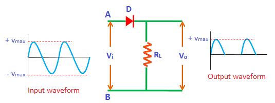
1.1 Positive Clipper Circuit
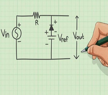
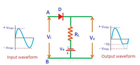
The diode in clipper circuit is connected in series to the input signal and that attenuates the positive portions of the waveform. The positive clamping circuit blocks the input signal when the diode is forward biased. During the negative half cycle of an AC signal, the diode is forward biased and allows electric current through it. In following figure, when the input signal voltage is lower than a preset upper limit voltage, the output voltage will change with the input voltage, however, when the input voltage reaches or exceeds the upper limit, the output voltage will remain at a fixed value, so that the signal amplitude is limited at the output.
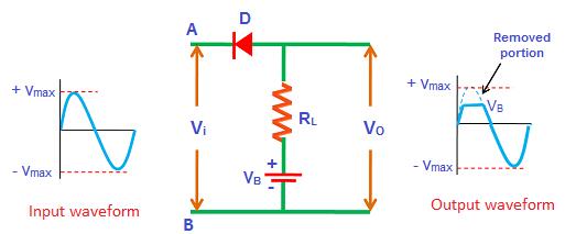
1.2 Negative Clipper Circuit
The diode in clipper circuit is connected in series to the input signal and that attenuates the negative portions of the waveform, is termed as negative series clipper. For the figure below, the diode is series to the input and output. If the diode has ideal switching characteristics, when iu is lower than E, D will not conduct, ou=E; when ui is higher than E, D will conduct, ou=iu. The limiting characteristic of this limiter circuit is shown in the figure.
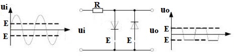
1.3 Combinational Limiter Circuit
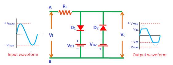
This kind of circuit combines the positive and negative limiters together which shows in the following figure.
2 Common Clipper Circuit Forms
Series clipper: The diode is connected in series with the load resistance.
Series Positive Clipper
The positive amplitude waveform is cut, and the negative amplitude waveform is retained.
Series Positive Clipper with Positive Bias
The positive amplitude waveform is cut, and the offset positive voltage is retained on the negative amplitude waveform.
Series Positive Clipper with Negative Bias

The waveform of positive amplitude is cut, and the negative voltage is shifted based on the waveform of negative amplitude.
Series Negative Clipper
The negative amplitude waveform is cut, and the positive amplitude waveform is retained.
Series Negative Clipper with Positive Bias

The negative amplitude waveform is cut, and the positive voltage is offset on the positive amplitude waveform.
Series Negative Clipper with Negative Bias
The negative amplitude waveform is cut, and the negative voltage is offset on the positive amplitude waveform.
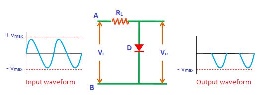
Shunt clipper: Diode in Parallel with Load Resistance
Shunt Positive Clipper
Shunt Positive Clipper with Positive Bias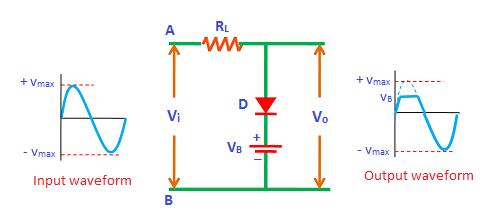
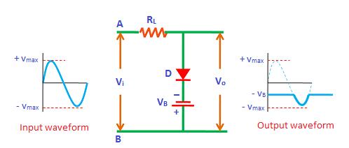
Shunt Positive Clipper with Negative Bias
Shunt Negative Clipper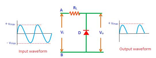
Shunt Negative Clipper with Positive Bias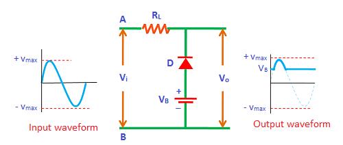
Shunt Negative Clipper with Negative Bias

Combination Clipper
When the positive and negative waveforms must be limited, a combinational limiter circuit is required.
Hey, Congratulations on reading! Get more info from Full Description of Clipper Circuit.