Introduction
In any power electronics converter, filter network, and communication system, where they are often used in Resonance Networks, inductors are the most common parts. If you are totally new to inductors, to learn the fundamentals, check out the post on implementing inductors. There are several kinds of inductors in practice, but none of them is an ideal inducer, meaning they are not pure inductors. Thus, aside from the inductance values, certain other parameters such as DC Resistance, AC Resistance, and Parasitic capacitance may often be correlated with an inductor while choosing an inductor for a specific application, and it must be regarded to satisfy the specification specifications and boost durability.
1 Why is Q Factor Important for an Inductor?
The matched functional part must be chosen based on the manufacturer's datasheet and product line cards after measurement of the inductance value for the selected application. It is necessary to consider the Quality Factor of the Inductor along with the Inductance value in some of the applications, particularly for RF-based applications.
2 Inductor Q Factor?
2.1 There are no Ideal Inductors
There would be no perfect part, as mentioned earlier in practice. The inductors are formed by winding the coils on cores called various magnetic materials. Any practical inductor's inductance value is obtained depending on the number of turns, permeability of the core material, flux density, core area, etc. The inductance value can adjust depending on applied current, signal frequency, aging variables, and operating temperature conditions, etc., when using these inductors in practical applications.
But for a wide range of frequencies, data, and temperature parameters, a stable design specification needs consistent output. So, in order to maintain the product's output accuracy, certain criteria are calculated to ensure the inductor's performance. One such parameter is the consistency factor of the coil or Q-Factor of an inductor.
2.2 What is Factor-Q?
The inductor can only have its inductance value in a perfect pure inductor. However, along with this nominal inductance value, fixed and variable resistance and parasitic capacitance will also be present in a functional inductor, which will reduce the inductance efficiency. By including this parasitic resistance and capacitance value, the Quality Factors or Q Factor is used to measure the inductor's efficiency. The Q-factor is a consistency calculation parameter that defines in a realistic application the “Quality of the Inductor” about its Losses and Performance.
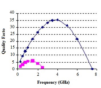
Figure 1. Q Factor in Inductors
Let's explore in depth this parasitic resistance and capacitance.
1) DC Resistance
The coils that are winded on magnetic core material during inductor manufacture have some internal resistance that introduces “DC resistance” along with the nominal inductance value. Designers can receive this resistance data in the “DCR” or “RDC” column of the manufacturer's datasheet. The value of an inductor's DC resistance depends on the wire length and the wire scale used for the winding phase. If the required inductance value is higher, it is necessary to wind more turns and use longer wire, which contributes to improved DC resistance (Figure 1 gives the details about resistance value for different wire sizes and lengths). Based on operating current, the inductors are manufactured and corresponding coil sizes are used for the specified applications. The resistance values are also depending on the wire size as well. Larger diameter coils yield lower DC resistance than lower diameter coils, but frequency-dependent parameters play a significant role in replacing a larger coil diameter with a shorter diameter coil.
2) Skin Impact Due to AC Resistance (Rac)
As the device is used roughly above the 50 kHz frequency range, the AC resistance plays the most dominant role in increasing wire resistance. The “Skin Effect” is known as this effect. Instead of traveling through the entire cross-section region of the conductor, as higher frequency signals (over 50 kHz) are applied through the conductor wires, the current would travel through the surface of the wires. The resistance is raised due to the non-use of the maximum coil region and this resistance value varies depending on the increasing frequency.
3) Core Hysteresis Impact Due to AC Resistance (Rac)
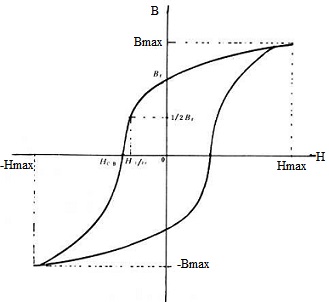
The difference in flux density would match the Magnetic(H) field variation in an ideal core. But due to structural characteristics, there may be minor differences in functional cores. For the Zero H Field applied, the flux density will not be zero due to residual magnetism and the flux density gets saturated after a certain H field. To carry down the residual magnetism Br to Zero, the extra repressive energy needs to be introduced in the opposite direction. The same strategy must also be followed in the negative cycle to allow the device work between the BH Curve's positive and negative regions. Dependent on the frequency applied, the BH curve and residual magnetism often differed, the loss of hysteresis increases with frequency rise. The Hysteresis loss would be applied along with the targeted inductance value in terms of AC resistance when shaping the inductor.
Figure 2. BH Curve
4) Resistance to Insulation (Rd)
To prevent internal short circuits, the main material and winding coils use insulation. The dielectric materials used in insulating materials have their own resistance, adding a valuable inductance value to the lossy component. This section is responsible for the leakage current, and the inter-wire capacitance has been created due to the dielectric materials.
The above-mentioned resistance values along with the nominal inductance values are present in a functional inductor. Other than the nominal inductance, the Total Resistance value is given by the relation below.
The Quality Factor (Q-Factor) provides information on the ratio between the components of the inductive reaction and the resistor that generate inductive losses during its operation. The Formula for Quality Factor is given below.
The Q factor can also be expressed in Power Relationship terminology. As previously mentioned, due to external parameters, the resistance components with the nominal inductance are added. This resistors will add losses to the inductor that reduce the efficiency of the inductor.
Based on the two relationships above, we can specify that if the resistance values of DC, AC, and Dielectric are high, the power loss is also higher and the value of the Q-Factor is lower. This would contribute to decreased results. If the Q value is high, the consumer may infer that the chosen inductor has lower AC and DC resistance levels, and thus has low power loss relative to lower Q-value inductor. Thus, the Q factor can provide the information regarding the efficiency of the inductor. Therefore, to get optimum efficiency from it, the Q value of the inductor should be high.
When design a circuit, on the basis of the specification and performance criteria, the designer should select the optimal Q factor values.
Because of the word limit, get the full note from Q Factor of Inductor Overview.