Thyristor diode modules are essential components in power electronics by enabling regulated rectification and power regulation. Proper testing of these components ensures consistent performance and prevents costly breakdowns. A multimeter is useful for diagnosing the thyristor diode module because it measures resistance and voltage.
Technicians who work with high-power electronic circuits and industrial equipment must understand this process, whether for troubleshooting or preventive maintenance. This blog will demonstrate how to test thyristor diode modules with a multimeter safely and effectively.
What is a Thyristor?
A thyristor is a semiconductor device that controls electrical power by acting as a switch. Positive terminals are called anodes, and negative terminals are called cathodes.
The control terminal regulates the current flow between the anode and cathode. The gadget has the unusual capacity to continue operating even without the gate signal. Because of this characteristic, it is the best option for high-power applications.
Lighting control, DC power sources, and AC motor control are just a few of the many uses for thyristors. Electronic circuits that need to control a fixed or variable amount of power can use them. By controlling electrical power effectively and dependably, the thyristor diode module offers more economical energy consumption and waste reduction.
Structure and Working Principle
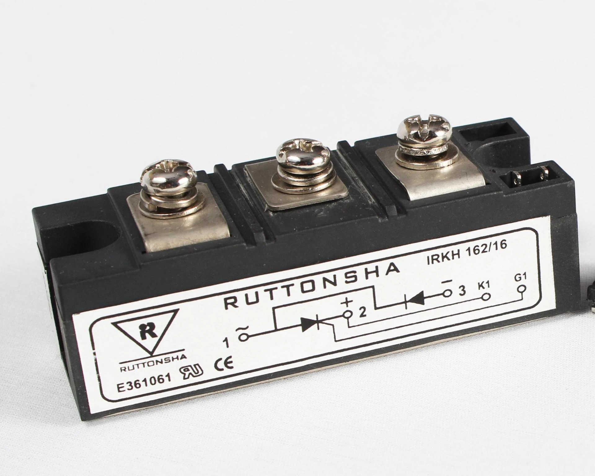
Several thyristors and diodes in a small container with heat sinks or cooling fins make up a typical thyristor diode module. Three terminals are present on thyristors.
Anode (A): Positive terminal
Cathode (K): Negative terminal
Gate (G): Conduction-triggering control terminal
When a positive pulse is applied to the gate, the thyristor turns on and allows current to flow between the anode and cathode. Until the anode to cathode current falls below a crucial threshold, it stays on.
The diodes are used for rectification. It allows electricity to flow exclusively in one direction and converts AC to DC. For power control systems to be reliable, thyristors and diodes must operate well.
Tools Required for Testing
To test a thyristor module, you will require.
A digital multimeter with diode testing mode.
Insulated gloves and safety goggles.
Wrenches and screwdrivers are needed to disassemble the module.
Isolation tools for safety during testing.
Security Measures
Power electrical module testing can be risky if appropriate safety measures are not followed. Consistently stick to these safety precautions.
Make sure the capacitors are drained and the module is unplugged from power sources.
Protect yourself from electric shock by donning insulated goggles and gloves.
Avoid coming into close contact with live components. Instead, you can use isolation tools as needed.
Ensure the multimeter is operating properly before using it.
Step 1: Visual Inspection
Undertake a visual inspection before testing electronically.
Look for physical damage.
Inspect solder junctions for cracks and cold soldering.
Review for corrosion or loose connections.
Step 2: Testing the Diode
Change the multimeter to the diode testing mode.
A strong diode has a forward voltage loss of roughly 0.5 to 0.7 volts. The diode could be shortened if the reading is zero or very low. It could be open if it reads "OL" (overload or endless).
Reverse the probes (black to the anode, red to the cathode). The reading should be "OL" or infinite, showing that reverse bias is properly blocked.
Step 3: Testing the Thyristor (SCR Mode)
Change the multimeter to resistance mode.
Connect the black probe to the cathode and the red to the anode.
Measure resistance in both directions. An "OL" reading in both directions suggests a reliable thyristor.
Test the gate by connecting the red probe to the gate terminal and the black probe to the cathode.
The multimeter's resistance should be modest (a few ohms), showing gate-triggering capabilities.
Step 4: Confirming Thyristor Firing
A 1.5V battery connects the positive terminal to the gate and the negative terminal to the cathode.
The multimeter should show low resistance by indicating that the thyristor has been triggered and latched on.
Step 5: Examining the Findings
A diode in good condition blocks in reverse and displays a forward voltage drop of 0.5–0.7V.
If a thyristor is not triggered, it will exhibit infinite resistance in both directions.
The module is most likely defective and requires replacement if any tests are unsuccessful.
Bottom Line
To determine the condition of these semiconductor components, testing thyristor diode modules with a multimeter is a simple but crucial procedure. You may find out whether the thyristor diode is operating properly or has malfunctioned by measuring the forward and reverse resistance. An excellent diode will block in one direction and conduct in another.
By preventing unplanned power electronics failures, routine testing of thyristor diode modules ensures reliable operation and minimizes downtime. Always unplug power sources and take safety precautions to prevent damage. With regular practice, using a multimeter to test thyristor diode modules becomes a quick and reliable method for maintaining electronic systems.


Sign in to leave a comment.