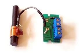
LC circuit refers to an oscillating circuit composed of a frequency selection network with an inductor L and a capacitor C, which is used to generate a high-frequency sine wave signal. Common LC sine wave oscillating circuits include a transformer feedback LC circuit and an inductive three-point LC circuit. And capacitive three-point LC oscillator circuit. The radiation power of the LC circuit is proportional to the fourth power of the oscillation frequency. To make the LC circuit radiate strong enough electromagnetic waves, the oscillation frequency must be increased and the circuit has an open form.
How does the lc circuit start to vibrate?
At the moment when the circuit is powered on, the capacitor will have a charging surge current. And this surge current will also change the inductor current connected to the capacitor. The electric stem thus produces an induced potential. This potential is added back to the two ends of the capacitor to make the charging current that has already ended fluctuate! This fluctuation in turn drives the change in the inductor current. This reciprocation continues, and oscillation occurs.
There are two main points here. One is that this oscillation will decay to disappear due to the impedance loss of the old and the circuit. So-called exhaustion oscillation! Sustaining the oscillation requires energy supplementation. This is why the oscillator circuit is complemented by an amplifier circuit.
Second, this oscillation has a very wide frequency spectrum. In order for it to have a main frequency, it must have a fixed frequency tank circuit. That is, the frequency selection loop.
1. LC oscillator start-up conditions
1.1. Amplitude condition of oscillator
The oscillator amplitude balance condition means that the feedback signal of the amplifier must have a certain amplitude. The theoretical formula indicates that the product of the feedback coefficient F multiplied by the voltage amplification factor AV of the amplifier is greater than 1, that is, AvF≥1, and the feedback coefficient F is a number smaller than 1, so it can be concluded that the value of Av should be Greater than 1. Correctly infer whether the amplifier is working in a normal state is the key to judging whether the oscillator is started. When the amplifier is amplifying normally, the external bias conditions of the triode must satisfy the forward bias of the emitter junction and the reverse bias of the collector junction. And it should be noted when judging: when studying the amplification state, it is to analyze the DC state of the oscillating circuit, not the AC circuit state. It should be remembered that in the DC state, the inductor coil is equivalent to a short circuit, while the capacitor is equivalent to an open circuit.
1.2 the phase balance conditions of the oscillator
The second necessary condition for oscillator start-up is that the phase balance should be satisfied, that is, the feedback signal of the amplifier should have the same phase as the input signal. The formula in the book indicates that the phase difference between the feedback signal VF and the input signal VI should be 2nπ ( n is an integer). Since VI and VF are in the same phase, the feedback signal can enhance the effect of the input signal. The specific judgment in the circuit is to see whether the circuit is positive feedback and to judge whether the circuit constitutes positive feedback, the instantaneous polarity method is generally used to judge. Before judging, it must be noted that the analysis of whether the phase is balanced is based on the AC state of the circuit, not the DC state, that is, the inductor coil cannot be regarded as a short circuit in the circuit at this time, and the two ends will have a certain voltage potential difference.


