Pressure transmitters transform pressure into current output usually expressed in milliamps (mA). They are usually set up for use in industrial settings where pressure readings need to be transmitted over long distances, or in harsh environments, with minimal signal loss. You won’t need to install additional circuitry or dedicated communication protocols unlike when using transducers and sensors.
Most pressure transmitters are calibrated starting from 4mA to 20mA such that even at zero pressure, 4mA current flows and the maximum output is 20mA. This is advantageous in several ways.
To begin with, it allows the instrument to represent measurements over a wide range of current (16mA to be exact). Setting 4mA as the output for the lowest pressure detected results in a ‘live zero’ making it easy to troubleshoot the instrument for broken wires or a faulty transmitter.
Meanwhile, setting the instrument to output only up to 20mA ensures electric safety. Pressure transmitters feed their readings to other components, limiting the maximum current they can output to 20mA, which ensures they don’t overload the system or cause a voltage drop in the system. Check out these transmitters from Microsensor.
How to Measure 4-20mA Current Loop Output
Now that you understand the reasoning behind the 4mA to 20mA calibration, here is a look at ways for measuring the current loop.
Using Process Clamp Meter
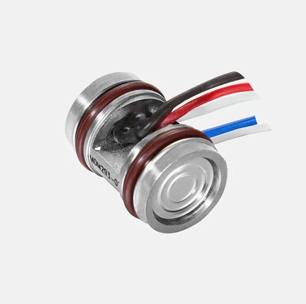
Take apart the transmitter till you reach the power and signal transmission wires. Do not break the 2-wire circuitTake your process clamp meter and connect it to the signal wiresTake the milliamps reading. Seeing as you didn’t break the circuit, the current should be flowing and the output must be in the 4mA to 20mA range. If the value lies outside this range, you need to troubleshoot and recalibrate the instrument
Using a Multimeter or a Loop Calibrator Tool
Get yourself either a multimeter or loop calibrator equipment for this process. It involves breaking or interrupting the power and signal transmission loop. Proceed as explained below:
Before beginning the measurement process, give your transmitter a look-see just to get an idea of its workingRemove the instrument’s cover to see the two-wire loop circuit.Set measurement function to mA dc then connect test ends for mA measureIdentify which of the loop wires is for signal transmission and disconnect one of its leads. Attach your loop calibrator or multimeter onto the end, making sure it’s in series with the transmitter wire. You’ve just broken or interrupted the power signal loop circuit to attach a measuring instrument. Read and record mA measurement.If the reading you get is not within the 4mA-20mA range, troubleshoot your equipment and recalibrate it
With the above steps, you should be able to measure the amount of current flowing through the power-signal loop wires of your pressure transmitter. If the live zero instrument is working properly, you should get readings within the 4-20mA range. Otherwise, troubleshoot the equipment and adjust its zero-point (z) and span (s) using the instructions in the user manual.
In case you need further advice, talk to experts. Microsensor technicians will be happy to help with any questions about pressure measurement instruments.


Sign in to leave a comment.