

Types of MV / LV power transformers
MV / LV power transformers are divided into transformers in insulating liquid (oil) and transformers in resin. There are also air transformers, but they are less used and therefore will not be treated.
MV / LV distribution transformers are typically machines capable of converting a three-phase voltage. They can consist of three independent single-phase transformers, but most often they are made with three primary and three secondary windings mounted on a single core with three parallel branches. The windings can be connected in star (code Y for medium voltage - code y for low voltage), in delta (code D for medium voltage - code d for low voltage) or zig-zag (code Zfor medium voltage - abbreviation z for low voltage). If the neutral (star point) is accessible, the code N is used on the medium voltage side and the code n on the low voltage side.
Since the most common MV / LV transformers have a delta connection on the medium voltage side and a star with neutral on the low voltage side, these have the descriptive code Dyn.
Resin transformers
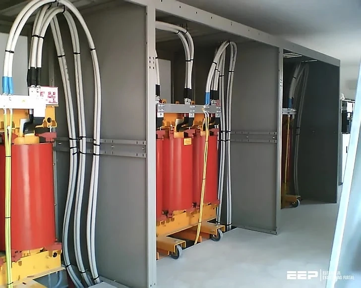
The resin transformers, sometimes also called dry transformers with incorporated windings, thanks to the evolution achieved in the construction techniques, are increasingly used for their reliability and for the lower environmental impact compared to oil transformers, as they reduce the risks of fire and of spreading pollutants in the environment. The medium voltage windings, made with wire coils or, even better, aluminum strips insulated from each other, are placed in a mold, in which the epoxy resin is poured under vacuum, to prevent gas inclusions in the insulators.
The windings are thus incorporated in a cylindrical, impermeable, mechanically sturdy casing with a smooth surface, which avoids both the deposition of dust and the action of polluting agents. The low voltage windings are generally made of a single sheet of aluminum, as high as the coil, insulated by means of a suitable material and heat treatment.
Transformers in insulating liquid
The oil transformers have the windings inserted inside a casing generally filled with mineral oil, which has the double function of guaranteeing adequate insulation between the windings and the masses and of dispersing the heat generated by the normal operation of the transformer itself. The oil increases in volume as the ambient temperature or the load of the transformer itself increases. To compensate for these volume variations, some transformers are equipped with an “expansion vessel”, located in the upper part which serves to compensate for the volume variations of the insulating liquid. This tank, defined as "conservative", communicates with the outside by means of filters that have the function of eliminating the humidity which, by accumulating, it could cause the dielectric properties of the oil to fail with consequent problems for the transformer itself. The dielectric strength of the insulating liquid can be seriously compromised by the ineffectiveness of the filtering system. For this reason the filters must be checked periodically and eventually replaced. Other types of oil transformers, on the other hand, do not include a conservator and the liquid is contained in the watertight casing, where the windings are located. In these types of transformers the volume variations are compensated by a lung of dry air and nitrogen which acts as a volume regulator. The problem with these transformers is that over time it is not possible to guarantee the tightness of this lung of air and nitrogen. The dielectric strength of the insulating liquid can be seriously compromised by the ineffectiveness of the filtering system. For this reason the filters must be checked periodically and eventually replaced. Other types of oil transformers, on the other hand, do not include a conservator and the liquid is contained in the watertight casing, where the windings are located. In these types of transformers the volume variations are compensated by a lung of dry air and nitrogen which acts as a volume regulator. The problem with these transformers is that over time it is not possible to guarantee the tightness of this lung of air and nitrogen. The dielectric strength of the insulating liquid can be seriously compromised by the ineffectiveness of the filtering system. For this reason the filters must be checked periodically and eventually replaced. Other types of oil transformers, on the other hand, do not include a conservator and the liquid is contained in the watertight casing, where the windings are located. In these types of transformers the volume variations are compensated by a lung of dry air and nitrogen which acts as a volume regulator. The problem with these transformers is that over time it is not possible to guarantee the tightness of this lung of air and nitrogen. Other types of oil transformers, on the other hand, do not include a conservator and the liquid is contained in the watertight casing, where the windings are located. In these types of transformers the volume variations are compensated by a lung of dry air and nitrogen which acts as a volume regulator. The problem with these transformers is that over time it is not possible to guarantee the tightness of this lung of air and nitrogen. Other types of oil transformers, on the other hand, do not include a conservator and the liquid is contained in the watertight casing, where the windings are located. In these types of transformers the volume variations are compensated by a lung of dry air and nitrogen which acts as a volume regulator. The problem with these transformers is that over time it is not possible to guarantee the tightness of this lung of air and nitrogen.
For transformers containing a quantity of oil greater than 500 kg, a special pit must be provided in the place of installation to collect any oil that may have leaked.
Construction characteristics of the windings
The magnetic core of the transformer consists of a pack of silicon steel laminations which normally has two alternative construction forms: with a column core and with a mantle core. In the column core type, each winding consists of two coils in series, each wound on a column of the transformer. In the mantle core type, both windings are wound on the center column of the core. The shell configuration minimizes the dispersed flow, the column configuration minimizes the quantity of laminations used.
MV windings can be made of tape or wire. The realization of the tape windings stresses the insulation placed between the turns to a lesser extent. In traditional windings, made with a conductor with a circular cross-section, each layer of the winding consists of a number n of side-by-side turns. In windings made with ribbon conductors, each layer consists of a single turn.
The LV winding, made by means of special winding machines, is composed of a single aluminum tape, with a mechanical height equal to the electrical height of the MV winding, with an integrated sheet of insulating material. Such winding guarantees to the winding itself a compactness such as to form a single cylinder resistant to possible axial and radial stresses, consequent to short-circuit phenomena. In resin transformers, this winding is then impregnated with epoxy resin.
Looking for High Voltage Instrument Transformers Manufacturers in Vadodara?
0