Building Information Modeling (BIM) workflows and tools create and manage 3D models while combining geometry, spatial relationships, and project information. Tools like laser scanning and drones improve accuracy, efficiency and collaboration to transform legacy workflows into innovative and data-driven processes.
Legacy surveying struggles with clash detection and design validation using manual measurements, siloed data and 2D drawings. Inaccuracies stemming from human intervention, incomplete site representation, and restricted collaboration lead to spatial issues, design errors, and costly rework.
Scan to BIM supports laser scanning firms, surveyors and engineering consultants with laser scanning to document accurate 3D data of physical structures while converting them into precise and data-rich 3D models. Accurate representation of as-built conditions aligns the physical space with digital plans. Combining spatial data mitigates discrepancies using Point Cloud for clash detection and supports design validation to reduce renovation, retrofitting and construction issues.
Understanding Scan to BIM
Scan to BIM converts point cloud data recorded from 3D laser scanners into precise parametric 3D BIM models. Scan to BIM workflows and tools such as ReCAP, Revit and Navisworks improve accuracy and coordination for renovation and retrofit projects with precise as-built conditions.
Process overview
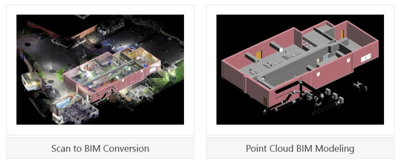
The Scan to BIM process uses LiDAR scanners to record spatial data while creating a 3D point cloud in X, Y and Z coordinates. This vast dataset is processed and transformed into a 3D parametric BIM Model embedded with attributes and structural components.
- Data collection using laser scanners (LiDAR)
High-resolution 3D laser scanners document the spatial geometry and surface attributes of the physical space.
- Point cloud generation
Raw point cloud data is converted into a point cloud while representing scanned surfaces using a 3D dataset.
- Conversion into a BIM model
The point cloud is segmented, analyzed and recreated into a 3D parametric model with well-defined attributes and elements.
Scan to BIM helps surveyors and engineering consultants leverage accurate as-built representations in digital space. Processing 3D laser scanned point clouds into 3D parametric models improves clash detection, validates design parameters, and mitigates spatial issues in construction, renovation and retrofitting.
Scan to BIM in Clash Detection
Clash detection in Scan to BIM flags spatial conflicts in the 3D digital model by assessing point cloud data from 3D laser scans integrated into the BIM model. It provides project teams with greater design integrity, lowers construction issues, and improves coordination across architectural, structural and MEP disciplines.
Clashes in Scan to BIM are defined as geometric interferences between multiple building elements, like mechanical ducts intersecting structural beams or plumbing fixtures overlapping electrical conduits. Real-time clash detection tools utilized to audit a BIM model flag these discrepancies and design inconsistencies during the preconstruction phase.
Role of Scan to BIM in Clash Detection and Design Validation
Scan to BIM improves clash detection and design validation through the conversion of accurate 3D laser scans into 3D models. Clash detection software, like Navisworks, identifies spatial issues and verifies design accuracy within the physical environment and digital space. This ensures every building system, like architecture, structure and MEP, aligns together for lower rework and improved project performance.
Accurate as-built data minimizes assumptions
High-performance as-built data from Scan to BIM models, which are extracted from 3D point clouds,prevent assumptions by providing geometrically accurate spatial data. This mitigates parametric modeling uncertainties, aligns designs with existing conditions, and improves computational reliability for retrofit planning and structural analysis.
Integration with BIM software for automated clash checks
Scan to BIM clash detection includes point cloud datasets into BIM tools, which enable automated interference detection through algorithmic spatial assessment with tools like Revit or Navisworks. This process identifies geometric issues, including MEP and structural collisions, which optimize interdisciplinary coordination, reduce manual computation, and enhance parametric model accuracy.
Define design validation
Design validation leads to a proposed design that aligns with project objectives and real-world scenarios. This verifies accuracy, compliance and feasibility. It includes analyzing spatial, structural and functional attributes versus goals and as-built data, which prevents misalignments that could lead to project delays and budget overruns.
How Scan to BIM enhances validation
Design validation with BIM provides accurate and real-world data from laser scans, which allows for a precise comparison between design models and as-built conditions. This ensures error-free renovation and retrofitting to lower rework.
Comparison of design intent vs. as-built conditions
The comparison of design intent vs. as-built conditions is driven by connecting laser scan data to the 3D model. 3D scanning for design validation serves as a high-resolution, precise digital representation of the built space.
Advanced software tools and algorithms support surveyors, engineering consultants, and laser scanning firms in highlighting differences in dimensions, geometry and spatial relationships between design and as-built models. Performing deviation analysis or interference detection helps participants quantify variations or highlight misalignments in the construction process. This method ensures alignment with the planned designed parameters to reduce rework.
Early identification of discrepancies
Quick identification of structural changes uses precise data from laser scans,which document as-built conditions through millions of point clouds. These point clouds are registered within the Scan to BIM model,and advanced tools assess deviation between design specifications and as-built geometry.
For example, structural misalignments, including column shifts, framing issues, and foundation-level problems, are flagged by comparing intended model tolerances with scanned data. The BIM model validation process enables quick intervention and facilitates corrective measures before actual construction starts. This reduces the risk of costly structural changes and ensures compliance with engineering standards.
Success Stories on Scan to BIM for Clash Detection and Design Validation
Clash Detection and Design Validation for a College Backyard Project in the UK
A building construction firm partnered with TrueCADD for Scan to BIM modeling of a mechanical house project in the UK. Providing .pcg files and images, the team at TrueCADD navigated challenges like missing information with 3D scans, management of large datasets, and incomplete 360-degree images. The team used Revit to import .pcg files and divided them into various sections.
A coordinated 3D Scan to BIM model at 10mm accuracy and LOD 300 was built incorporating architectural, structural and equipment spacing. Missing information was retrieved through interpolation.
Handing over the deliverables to the client led to:
- Complete digital documentation on cloud-based software
- Informed decision making
- Mitigated risks
- Reduced costs
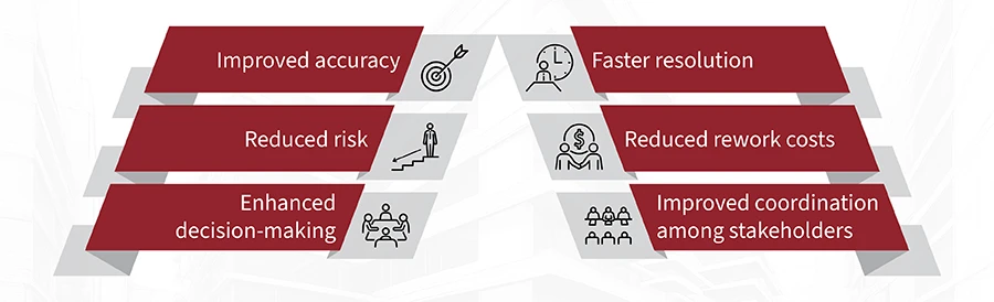
Benefits of Scan to BIM for Clash Detection and Design Validation
Scan to BIM improves clash detection by embedding accurate and real-world data into the design model. This provides quick conflict identification, improved design accuracy, and a reduction in costly errors during renovation and retrofitting. Validating as-built conditions vs. designs optimizes workflows and enhances project quality.
Step by Step Workflow for Scan to BIM for Clash detection and Design Validation
The workflow for Scan to BIM starts with capturing precise point cloud data using laser scanners, followed by aligning scans with the 3D model. Furthermore, interference detection tools assess ambiguities between design and as-built models. This highlights potential issues to be resolved before on-site work starts.
- Process Data: Clean and align point cloud data in software using Recap
- Create BIM Model: Convert point cloud to 3D BIM model in Revit
- Integrate Models: Overlay as-built BIM with the design model in Navisworks
- Run Clash Detection: Identify conflicts (e.g., MEP vs. structure) using automated checks
- Validate Design: Compare design to as-built data for discrepancies
- Resolve Issues: Adjust design and recheck for precision
- Document Results: Export updated BIM and reports for handover
- Implement: Use the model onsite, updating during construction
Conclusion
The future of construction requires the streamlined integration of reality capture tools with digital workflows. Scan to BIM is at the forefront and helps surveyors, engineering consultants, and laser scanning firms with automated clash detection and AI-led design validation. This enhances accuracy, reduces project risks and mitigates rework. Embracing Scan to BIM can lead to error-free, efficient and smarter construction that creates a digitalized, as-built environment.


Sign in to leave a comment.