

Time-of-Flight (TOF) cameras are the core of modern 3D depth sensing, widely applied in robot navigation, industrial inspection, biometric recognition, AGV automation and intelligent surveillance. Most engineers focus on sensor tuning and point cloud algorithm optimization to improve depth accuracy, yet easily ignore TOF lens distortion — a key factor causing persistent depth errors, point cloud distortion and unstable device performance.
Different from ordinary RGB lens distortion that only affects visual presentation, TOF lens distortion directly interferes with infrared depth calculation, resulting in Z-axis distance deviation and inconsistent edge imaging. This article analyzes the causes and harms of TOF lens distortion, shares practical optimization methods, standard selection principles and common troubleshooting answers, helping you effectively minimize distortion and achieve stable high-precision 3D sensing.
What Is TOF Lens Distortion & Its Unique Challenges
Lens distortion refers to the geometric deformation of imaging caused by optical design limitations. For professional TOF depth sensing systems, distortion is divided into two core types, both bringing unique risks to infrared imaging.
Radial distortion is the most common issue, including barrel distortion and pincushion distortion. Wide-FOV TOF lenses usually produce obvious barrel distortion, where the edge imaging is stretched and deformed, with error far exceeding the central area.
Tangential distortion is mainly caused by lens assembly deviation, optical axis tilt and manufacturing tolerance. It is particularly prominent in compact M12 TOF lenses for embedded devices, easily causing irregular depth offset in local imaging areas.
TOF systems work exclusively at 850nm and 940nm infrared wavelengths, bringing exclusive pain points: ordinary IR lenses lack targeted spectral optimization, resulting in severe focus shift and increased distortion under infrared light. In addition, mismatched chief ray angle (CRA) and insufficient image circle coverage will further amplify edge noise and distortion errors, seriously affecting depth detection accuracy.
Practical Impacts of Uncontrolled TOF Lens Distortion
Slight lens distortion is negligible for low-precision consumer devices, but it will trigger obvious functional failures in industrial and commercial TOF scenarios.
In robot SLAM and AGV navigation, distorted point clouds lead to positioning drift, obstacle misjudgment and navigation failure. In industrial precision measurement and PCB detection, distortion causes dimensional detection data to exceed the error threshold. For facial recognition and biometric identification systems, edge feature offset reduces recognition accuracy and stability. In drone aerial surveying and 3D reconstruction scenarios, lens distortion will cause overall deformation of panoramic point cloud data and fail to meet industrial calibration standards.
Core Parameters to Judge TOF Lens Distortion Performance
Many buyers simply take the distortion percentage as the only evaluation standard, which is inaccurate. Excellent low-distortion TOF lenses need to meet multiple parameter standards at the same time.
First is distortion control level. Ordinary general-purpose TOF compatible lenses have a distortion rate of 2%-5%, which is only suitable for low-precision scenarios. Industrial-grade low-distortion TOF lenses can control the distortion within 0.5%, fully meeting high-precision measurement and navigation needs.
Second is infrared spectral optimization. Professional TOF lenses are calibrated for 850nm/940nm VCSEL wavelengths, with stable infrared imaging and no focus shift. Ordinary visible light lenses will have severe distortion drift in infrared mode.
Besides, CRA matching degree, complete sensor image circle coverage and precision metal mounting structure are also key indicators to suppress distortion. Precision manufacturing can effectively avoid assembly-induced tangential distortion, while complete image circle coverage eliminates edge distortion dead zones.
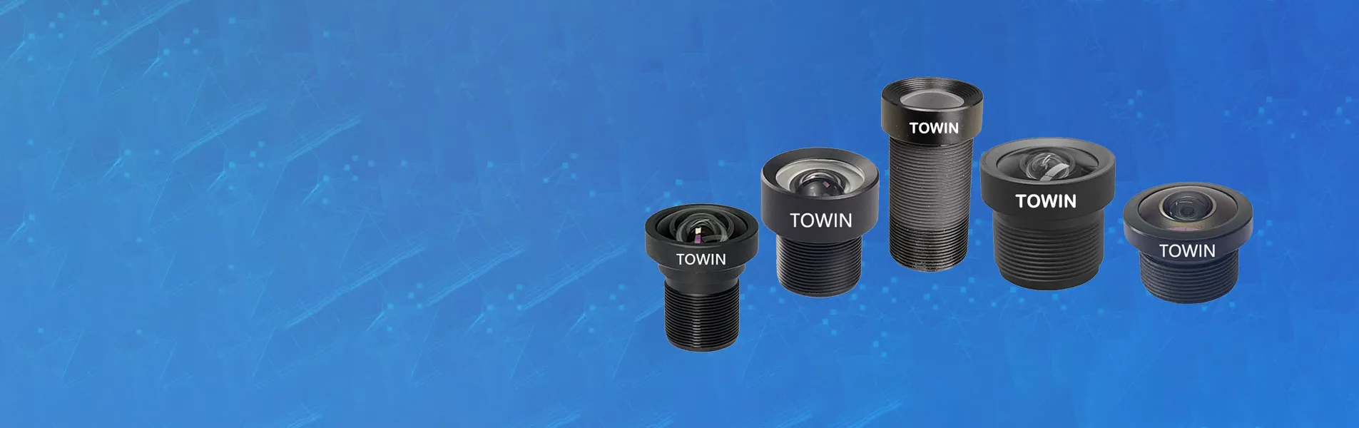
For stable and reliable industrial TOF lens solutions, you can refer to professional manufacturers focused on machine vision optics: https://www.towinlens.com/
Effective Methods to Minimize TOF Lens Distortion
Eliminating TOF distortion requires a combination of hardware selection, assembly optimization and software calibration. Hardware optimization is the core, and software calibration is only an auxiliary means.
1. Hardware Preference: Fundamental Distortion Control
Select dedicated IR-corrected low-distortion TOF lenses instead of universal IR lenses. Prioritize products with clear 0.5% low distortion parameters, sensor-matched CRA design and full image circle coverage. For mass production projects, choose metal mount lenses to avoid deformation and offset of plastic structures, ensuring long-term stable optical performance.
2. Standardized Mechanical Assembly
Most manual assembly errors induce tangential distortion. Keep the lens and sensor plane strictly parallel and coaxial, avoid over-tightening the thread to prevent lens tilt. Equip the module with a light shield to block stray infrared light, avoiding distortion-like depth noise interference.
3. Scientific Software Calibration Compensation
Adopt the Brown-Conrady distortion model to calibrate radial and tangential distortion coefficients of the lens. Different from ordinary image correction, TOF calibration must synchronously correct depth map point cloud data, not only 2D pictures. It is worth noting that software calibration has limitations — it cannot make up for congenital optical design defects, and excessive correction will reduce the effective field of view.
4. Scenario-Based Application Optimization
In actual use, place key detection targets in the central field of view with the smallest distortion. For scenarios requiring both wide FOV and high precision, customize exclusive optical solutions to balance viewing angle and distortion control.
FAQs
Q1: Can ordinary M12 IR lenses replace professional TOF lenses?
A: No. Ordinary IR lenses are optimized for visible light, with uncalibrated infrared distortion and mismatched CRA, which will cause unstable depth data and cannot be used for industrial high-precision TOF equipment.
Q2: What distortion value is qualified for industrial TOF applications?
A: General robot navigation allows distortion below 1%, while precision measurement, biometrics and industrial detection require strictly controlled distortion within 0.5%.
Q3: Can software calibration completely eliminate TOF lens distortion?
A: Impossible. Calibration only compensates partial measurable residual distortion, but cannot solve congenital problems such as poor optical design and insufficient image circle. High-quality hardware is the premise of low distortion.
Q4: How to quickly judge whether depth error is caused by lens distortion?
A: Shoot a flat plane with the TOF camera. If the central point cloud is normal and the edge is obviously bent and deformed, lens distortion is the main cause.
TOF Lens Selection Checklist for Low Distortion
Confirm the lens infrared wavelength matches the VCSEL sensor; check the official low distortion parameter index; verify the image circle fully covers the sensor size; confirm CRA parameter matching; prefer precision metal mount structure; complete lens calibration before mass deployment; conduct real machine sample testing for high-precision projects.
Conclusion
TOF lens distortion is a comprehensive problem caused by optical design, spectral adaptation, manufacturing tolerance and assembly technology. To minimize distortion and stabilize 3D depth sensing performance, enterprises must prioritize professional low-distortion TOF lenses at the hardware level, assisted by standardized assembly processes and accurate software calibration.
Blindly relying on algorithm optimization to make up for lens defects will only lead to unstable equipment performance and increased after-sales costs. Choosing industrial-grade customized TOF optical solutions is the most cost-effective way to ensure long-term stable operation of 3D vision equipment.






















Sign in to leave a comment.