Introduction
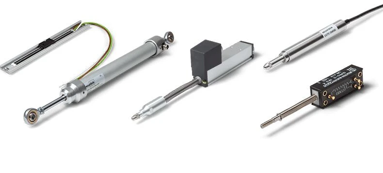
Linear Displacement Sensor, also called Linear Transducer or Linear Potentiometer Sensor, is a device used to monitor and measure linear position, which convert mechanical physical quantities into electrical signals. Linear potentiometer is a type of variable resistance sensor, designed to measure the displacement of a slider or wiper in a linear direction. Also known as a slider or pot, linear potentiometers produce a changing rate of resistance, dependent on the position of a slider or wiper.
[caption class="snax-figure" align="aligncenter" width="1140"][/caption]
1 Linear Displacement Sensor Working Principle
The function of the linear displacement sensor is to convert the linear mechanical displacement into an electrical signal. In order to achieve this effect, the sensor slide rail is connected to a steady-state DC voltage, allowing a small current of microamperes to flow, and the voltage between the slide and the starting end is proportional to the length of the slide. Using the sensor as a voltage divider can minimize the requirements for the accuracy of the total resistance of the sliding rail, because the resistance change caused by the temperature change will not affect the measurement result. The linear displacement sensor is actually a sliding rheostat. Using the sensor as a voltage divider can minimize the requirements for the accuracy of the total resistance of the sliding rail, because the resistance change caused by the temperature change will not affect the measurement result.
2 Linear Potentiometer Sensor Design Parameters
For the general linear displacement sensor:
Wear resistance life: >100X106 times
Linear accuracy error: <0.05%
Repeatability error: <0.005mm
Maximum moving speed: 10m/s
Impact factor: IEC 68-2-29:1968 50g
Vibration factor: IEC 68-2-6:1982 20g
Maximum allowable voltage: DC60V/5KΩ~20KΩ; DC36V/2KΩ~4KΩ; DC24V/1KΩ
Temperature drift coefficient: <1.5ppm/℃
[caption class="snax-figure" align="aligncenter" width="1140"][/caption]3 Linear Transducer Applications
1) KTC, KTM, LS tie rod structure is a general structure, with optional pull ball universal head or universal head, can reduce the adverse effects caused by the installation of non-neutral. They are suitable for injection molding machines, textile machinery, woodworking machinery, etc.
2) KPC and KPM fixed belts at both ends are hinged and sporty, suitable for swinging, and in measurement systems where the sensor body cannot be fixed, and the sensor will move with the measurement movement.
3) KTF and KFM slider types are suitable for the application of the smallest installation length size. With the extension arm, it can eliminate the adverse effects of installation misalignment.
4) KTR type is a miniature self-recovery rod structure, no need to tow and install.
5) KPF type can also detect the internal displacement of the cavity.
[caption class="snax-figure" align="aligncenter" width="1140"][/caption]
4 Linear Potentiometer Sensor Installation
1) The installation of the linear displacement sensor should balance two ends. Do not tighten the fixing bracket screws before the limit position is determined. The linear displacement sensor fixing bracket screws can be locked after adjusting the stroke.
2) The pull-ball universal head of the tie-rod displacement sensor allows a centering deviation with a radius of 1mm. Of course, the shorter the specification, the smaller the centering deviation is recommended.
3) After fixing the linear displacement sensor, when retracting the tie rod, the cylindrical body of the universal ball head should be able to have gaps in the four radial directions. Or adjust the mounting position of the universal head or the mounting bracket position near the extended end.
4) If there is a big misalignment when the pull rod is pulled out, adjust the mounting bracket near the end of the plug. This can be used as an auxiliary review method.
5) The mounting rod of the pull ball universal head and the pull rod are allowed to tilt at an angle of 12°. However, if the centering deviation and tilt deviation are both large during installation, the stability and service life of the electronic ruler will be affected. So further adjustment is required.
6) The slider electronic ruler can reduce the workload of adjusting the neutrality, but the auxiliary extension rod cannot be cancelled. Because the stability and service life due to the poor neutralization will occur, and even damage the sensor.
7) After all adjustments are made, tighten the mounting screws to make the grounding resistance less than 1. Measure the resistance between the cover screw of the potentiometer sensor and the mounting bracket with a multimeter in the 200 block.
8) When using a four-wire system or wiring with a shielded wire, the grounding end of the linear potentiometer should be connected, and the fourth end or shielding wire should be grounded at the end of the electric control box correctly.
[caption class="snax-figure" align="aligncenter" width="1140"][/caption]
5 Linear Displacement Sensor Use Matters
1) If the potentiometer sensor has been used for a long time, and the seal has been aging, there are a lot of impurities mixed in, and the water mixture and oil will seriously affect the contact resistance of the brush, which will cause the displayed number to jump continuously. At this time, it can be said that the electronic ruler of the linear displacement sensor has been damaged and needs to be replaced.
2) If the capacity of the power supply is small, there will be many situations. Therefore, the power supply should have sufficient capacity. Because insufficient capacity will cause the following situation: The movement of the melt will change the display of the sensor to cause the fluctuations, resulting in a large error in the measurement result.
3) FM interference and electrostatic interference may cause the digital scale of the linear displacement sensor to jump. The signal line of the sensor and the strong current line of the equipment should be separated from the wire duct. Use the grounding support to have good contact with the ground. The signal wire needs to use a shielded wire, and a section of the electrical box should be grounded to the shielded wire.
4) The power supply voltage must be stable. The industrial voltage needs to meet the stability of ±0.1%. For example, if the reference voltage is 10V, a fluctuation of ±0.01V can be allowed. If it is not, it will cause a display fluctuation. But if the amplitude of the display fluctuation at this time does not exceed the amplitude of the fluctuation voltage, then the potentiometer sensor is normal.
5) As for the linear displacement sensor installation, the parallelism can be allowed to have an error of ±0.5mm, and the angle can be allowed to have an error of ±12°. However, if both are too large, then the display number will be bounced. So the parallelism and angle must be adjusted.
If you want to get the full details of it, you can visit Introduction to Linear Potentiometer Sensor Basic.
Sign in to leave a comment.