

Traditional line distance relay testing procedures (MTA, Reach, and Timing) are a great way to test electro-mechanical relays and learn how line impedance relays operate; but they are inefficient, ineffective, and frustrating when applied to modern digital relays. This post will show you why your traditional tests are probably failing, and the next post will show you how to perform a dynamic, or system, line distance protection relay testing procedure that will work on any modern relay using any test-set.
If you don’t have a good understanding of line impedance protection, I suggest you stop now and read the “Line Distance (21) Element Testing” Chapter in The Relay Testing Handbook: Principles and Practice, and watch the following video series:
A New Transmission Line Protection (21) VideoUnderstanding Distance Protection (21) VideoYou can also play with the following animation to make sure you truly understand line distance protection.
Can You Predict What Happens Inside a Distance Protection Relay?
What Does a Traditional Line Distance Protection Relay Testing Procedure Look Like?
Let’s look at the traditional methods for line distance protection testing that many relay testers, and automated software, use to test line impedance protection:
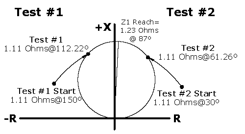
Maximum Torque Angle (MTA) Tests
An MTA test starts on one side of a circle characteristic and changes the angle until a pickup is detected. Then a second test starts on the other side of the circle and ramps the phase angle in the other direction. The MTA is assumed to be half-way between the two points.
Why would you perform an MTA test?
This is a quick way to tell whether an electromechanical relay (ABB/Westinghouse-KD, or GE GCX) is operating close to the specified characteristic. If the MTA results are good, your multiple-point reach test has a good chance of passing. If the results are bad, you might only test a few key points at first while you wrestle the relay into submission before you run the full battery of tests. This test is really a way to speed up the relay calibration procedure, not to determine a specific number.
Why wouldn’t you perform this test on a digital line distance protection relay?
There’s nothing to calibrate in a digital line impedance distance relay, so this test won’t speed up the digital relay test procedure. It will only slow us down! We’ll be able to tell the Maximum Torque Angle (MTA) using our dynamic tests. Some other reasons not to do this test include:
There could be hidden blinders as described in the next section that will cause some points to fail, especially if the current lags by more than 90 degrees.You can get a false positive on some test-sets if the relay doesn’t operate at all.You can get a false positive if another element, like overcurrent, operates instead.You can only test the outer circle without changing the relay settings, and only if the test does not trigger another element to operate first.You need to change settings to test the inner MHO characteristics, which means you’ll probably do the rest of your tests when the relay is reprogrammed to isolate the element under-test. Now you are testing an unreal condition and will have no way to know whether the output relay is programmed correctly, or whether some other element is incorrectly programmed and will prevent this element from operating.Reach Tests Across the Entire Line Distance Protection MHO Relay Characteristic
A traditional line distance protective relay reach tries to test the entire MHO characteristic as shown in the following image. This test applies current and voltage at a variety of test angles to make sure the MHO impedance protection is really a circle.
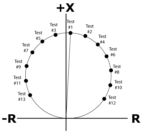
Why would you perform this test?
A really good electromechanical relay tester could look at the test results for this test and know exactly which resistor/inductor/capacitor to adjust, hoping to bring the KD or GCX relay into calibration. Because the relay can naturally fall out of calibration, a good selection of test points are required to make sure the relay will operate correctly throughout the entire range.
Why wouldn’t you perform this test on a digital line distance protection relay?
Digital relays either work, or they don’t. There’s nothing to calibrate, so the big reason for performing multiple tests across an entire range doesn’t exist. Digital relays simply don’t fail this way. In fact, here are some reasons why a complete characteristic test will fail if you try to run it on a modern relay:
Line Impedance Distance Relay Specifications
Manufacturers typically specify that the line impedance protection will only operate within a certain range, such as:
SEL-311C = “±5% of setting at line angle for 30 ≤ SIR ≤ 60” or “±3% of setting at line angle for SIR < 30”GE D-60 = “±5% including the effect of CVT transients up to an SIR of 30.”ABB REL670 = “±2.0% static accuracy, Conditions: Voltage range: (0.1-1.1) x Vn, Current range: (0.5-30) x In, Angle: 85 degrees”SIEMENS SIPROTEC 7SA522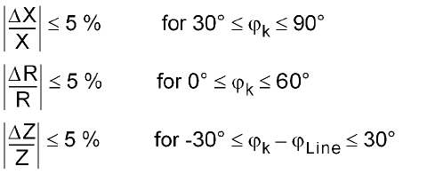
Did you notice all those caveats about the tolerances? Let’s dig a little deeper:
Line Impedance Protection Angle Specifications
The SEL relay is only guaranteed to operate at the line angle (Z1ANG). The ABB relay is only guaranteed to operate at 85 degrees. The SIEMENS relay has a wider range, but there are still limits.
If you run a test outside those values or ranges: What are the expected tolerances? There aren’t any! If you don’t know what is a pass or fail at a given test point, why are you performing the test?
These narrow operating ranges might seem arbitrary, but they exist because digital relays are much smarter than the electromechanical relays they replaced. The circle, or MHO, characteristic exists because of the mechanical limitations of electromechanical relays, and most digital relays just keep up the tradition. A large portion of that characteristic can’t happen during a fault on the power system as described in these blog posts:
If you try to perform a test where the fault current lags the fault voltage by more than 90°, the relay may apply a hidden directional blinder that tells the relay: “That’s not a real fault; don’t trip”. If you try to apply a fault condition where the fault current lags the fault voltage by less than 40°, there may be another blinder that tells the relay: “That’s not a line fault. That looks more like an overload. Don’t trip!”
A modern line distance impedance relay is applied to protect the system from line faults. They are smart enough to know the difference between a relay tester trying to get numbers on their test sheet and a real transmission line fault. Don’t try and force your 20th century relay test plan (square peg) on your 21st century relay (round hole)! They aren’t compatible.
Line distance Impedance Protection Source Impedance Ratios (SIR)
SIR stands for the Source Impedance Ratio. You probably learned about source impedances if you think waaayyyy back to your basic electrical circuit classes. Any given circuit will have a source (100V) that provides a voltage and a load that has some impedance (100Ω), which creates current (1.0A) via Ohm’s Law as shown in the following image:
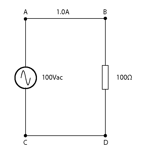
You should have graduated beyond the simple circuit, and started including wire and source impedance into the circuit as shown in the next drawing:
The measurement across A and C is still 100V and 100Ω, but the source is actually creating 101V with a 1V drop across its internal impedance. What happens if we have a fault and the external resistance drops to 8Ω? Will the voltage across A & C still be 100V? Will the current rise to 10A? Let’s see: