
Battery Shipping Shock Testing Standard
T.4 Test li-polymer battery and lithium-ion battery shall be secured to the testing machine employing a rigid mount that will support all mounting surfaces of each test battery. Each battery cell shall be subjected to a half-sine shock of peak acceleration of 150gn and pulse duration of 6milliseconds. Alternatively, large cells may be subjected to a half-sine shock of peak acceleration of 50gn and pulse duration of 11milliseconds. The pulse duration shall be six milliseconds for the small battery and 11milliseconds for the large battery.
Cells and batteries meet this requirement if there is no mass loss, no leakage, no venting, no disassembly, no rupture, and no fire and if the open-circuit voltage of each test cell or battery after testing is not less than 90% of its voltage immediately prior to this procedure. The requirement relating to voltage is not applicable to test cells and batteries at fully discharged states.
Similar to UN38.3 but UN 38.3 says that the open circuit voltage of each test cell or battery after testing is not less than 90% of its voltage immediately prior to this test. IEC 62281 there shall be no short-circuit during the test.
a) Purpose This test simulates rough handling during transport.
b) Test procedure
Test cells and batteries shall be secured to the testing machine by means of a rigid mount that will support all mounting surfaces of each test cell or battery. Each test cell or battery shall be subjected to 3 shocks in each direction of three mutually perpendicular mounting positions of the cell or battery for a total of 18 shocks. For each shock, the parameters given in Table 7 shall be applied: The test shall be conducted using the test cells and batteries previously subjected to the vibration test.
Requirements. There shall be no leakage, no venting, no short-circuit, no rupture, no explosion, and no fire during this test.
a) Requirement: Shocks encountered during handling or transportation shall not cause fire, explosion, or leakage.
b) Test The fully charged cell or battery is secured to the shock testing machine by means of a rigid mount that will support all mounting surfaces of the cell or battery. The cell or battery is subjected to a total of three shocks of equal magnitude. The shocks are applied in each of three mutually perpendicular directions. At least one of them shall be perpendicular to a flat face.
For each shock, the cell or battery is accelerated in such a manner that during the initial 3 ms the minimum average acceleration is 735 m/s2 (75 g,). The peak acceleration shall be between 1 226 m/s2 (125 g,) and 1 716 m/s2 (175 g ).cells or batteries are tested at an ambient temperature of 20 °C±5 ℃. After the test, the sample shall be put on rest for a minimum of 1 h and then a visual inspection shall be performed.
c) Acceptance criteria: No fire, no explosion, no leakage.
The fully charged cell or battery is subjected to a total of three shocks of equal magnitude. The shocks are applied in each of three mutually perpendicular directions. The acceleration is an average of 75g within initial 3ms, the peak is between 125g and 175g.
The component lithium-ion cell has been approved by Underwriter Laboratories Inc., according to UL1642.
16.1 The lithium cell is to be secured to the testing machine by means of a rigid mount that supports all mounting surfaces of the cell. Each cell shall be subjected to a total of three shocks of equal greatness. The shocks are to be applied in each of three mutually vertical directions unless it has only two tomahawks of symmetry, in which case only two directions shall be tested. Each shock is to be applied in a direction normal to the face of the cell. For each shock, the lithium-ion cell is to be accelerated in such a manner that during the initial three milliseconds, the minimum average acceleration is 75 g (where g is the local acceleration due to gravity). The peak acceleration shall be between 125 and 175 g. The lithium-ion cells shall be tested at a temperature of 20 ±5°C (68 ±9°F). 16.2 The samples shall not explode or catch fire.
(75g average through 3 ms, 125g to 175g peak, 3 axes, 3X) The lithium-ion cell is to be secured to the testing machine using a rigid mount that holds all mounting surfaces of the lithium-ion cell. Each chamber shall be subjected to a total of three shocks of equal magnitude. The shocks are to be applied in each of three mutually perpendicular directions unless it has only two axes of symmetry, in which case only two courses shall be tested. Each shock is to be applied in a direction normal to the face of the cell. For each blow, the lithium-ion cell is to be accelerated in such a manner that during the initial 3 milliseconds, the minimum average acceleration is 75 g (where g is the local acceleration due to gravity). The peak acceleration shall be between 125 and 175 g. Cells shall be tested at a temperature of 20 ± 5°C (68 ± 9°F). The samples of lithium-ion batteries shall not explode or catch fire.
Purpose: Validate the ability of the host device to withstand shock and vibration caused by normal usage. Ensure the host does not propagate faults to the battery pack and cells when they are installed in the system.
Procedure: Prior to subjecting samples to testing, initial mass and voltage must be measured and recorded. The host shall be subjected to a half-sine shock with a peak acceleration of 300 m/s2 minimum and a pulse duration of 6 milliseconds. The exposure shall consist of 3 shocks in the positive direction followed by 3 shocks in the negative direction while secured in 3 mutually perpendicular positions for a total of 18 shocks.
Compliance: No mass loss (beyond allowable limits), no short-circuit, No abnormal heating, no smoke, no fire, no explosion and / or leakage from battery pack or host.
Perform the test according to ISO
16750-3: half-sine shock 50g 6 ms, 10 times in the same direction as the acceleration of the shock occurs in the vehicle.
6.2 Mechanical shock.
6.2.1 Purpose
The purpose of this test is to verify the safety performance of the DUT under a mechanical load due to mechanical shock, which a battery system will likely experience during the normal operation of a vehicle.
NOTE Mechanical shock considers driving operations, such as deceleration in sudden braking situations or driving over road bumps or potholes. It does not include a vehicle crash scenario. This test is applicable to packs and systems intended to be mounted at rigid points of the body or on the frame of a vehicle. The test shall be performed according to half-sine: 50g 6ms, 10 shocks per test direction, or according to a test profile determined by the customer and verified to the vehicle application. Acceleration from the shock in the test shall be applied in the same direction as the acceleration of the shock that occurs in the vehicle. If the direction of the effect is not known, the DUT shall be tested in all six spatial directions.
Shock testing is labeled as optional at the cell level. UN38.3 is to be applied to cells. For pack: half-sine 25g, 15ms 18 ea. shocks = XYZ negative & positive directions x 3 times.
4.2.1 SHOCK TEST (MODULE LEVEL OR ABOVE)
4.2.1.1 Test Description—Subject the ECSS to shock events at one or more defined shock levels. The low-level shock is a robustness test that an ECSS will generally survive without damage. The mid-level shocks are more severe and the ECSs may be inoperable after the test. Shock levels and durations are defined in Table 2. Each shock level is specified in terms of a velocity change and a corresponding maximum duration. (Shock duration is defined as the time between 10% and 90% of the peak value.) Achieving this velocity change over this maximum duration is the goal of the test; however, the characteristics of the acceleration (deceleration) pulse are limited by the test equipment used.
The maximum duration places lower limits on the peak acceleration which must be seen during the test. For example, for the low-level test, the lowest possible acceleration meeting the requirements would be achieved if the acceleration was an ideal square wave of about 12.5 g. The minimum peak acceleration in Table 2 is specified at about twice this level, recognizing that an ideal square wave cannot be achieved in the real test. It is expected that a simple pulse shape (such as a half-sine) will be used for the test, but the pulse shape is not specified to allow as much flexibility as possible in the testing laboratory. Advanced techniques which more accurately simulate actual deceleration time histories are not excluded. lt is generally in the interest of the ECSS manufacturer to keep the pulse duration as long as possible while meeting the specification. However, if the ECSS is robust, it may be desirable to increase the peak acceleration and/or reduce the duration if this reduces test complexity and cost.
• Cells: follow UN/DOT 38.3
•small cells/batteries (150g/6ms, 3 axis, +/-, 3X repeat) •large cells/batteries (50g/11ms, 3 axis, +/-, 3X repeat)
• Packs: 25g, 18 ms, 3 axis, +/- directions, 3X repeat) No rupture, fire, explosion, or loss of isolation
4.5 Mechanical Shock
Rationale: This condition simulates inertial loads which may occur during a vehicle crash situation. The battery system shall meet the requirements in 4.5.3 when tested according to one of the following two alternatives.4.5.1 Alternative 1: Battery System-Level Evaluation Condition: The complete battery system is to be tested, with the following exceptions/ clarifications, in accordance with one of the following options: UN Test Manual,Test T.4; or SAE J2464, Section 4.3.1. Exceptions/Clarifications: Evaluations, one repetition each, are to be conducted in the positive and negative directions of the primary vehicle longitudinal and lateral axes, as installed, for a total of 4 separate evaluation conditions. it is not required that all evaluation conditions be conducted on a single test sample. The battery system shall be firmly secured to the test fixture. Note that, while battery modules or sections may be individually tested in accordance with UN requirements, a complete battery system is to be tested for this condition, except as allowed per 4.1.3. NOTE: For battery systems with mass<100 kg, a shock test may need to occur using a crash simulation sled, or similar device. 4.5.2Alternative 2: Vehicle-Level Evaluation Condition: The complete battery system is to be assessed following vehicle tests simulating front, rear, and side impacts, as defined in FMVSS 305,S6.1,6.2,6.3 (or equivalent regionally applicable vehicle front, rear, and side crash conditions)with the following exceptions/clarifications: Battery state of charge (SOC) shall be at 95-100% of the maximum which is possible during normal vehicle operation and battery temperature shall be 25 C±5°C(or as specified in equivalent regionally applicable regulations). 4.5.3 Requirements The following requirements are to be met following the test for either alternative selected.
During the test and for a minimum 1 hour post-test observation period, the battery system shall exhibit no evidence of battery enclosure rupture, fire,or explosion and shall maintain high voltage to ground isolation of no less than 100 Qv.lsolation measurements are to be done in accordance with ISO 6469-1,6.1.3; or equivalent. For Alternative 2, the battery system shall be retained at its mounting location (per SAEJ1766, Section 4.4.2).
A fully charged sample is to be subjected to the Shock Test in accordance with SAE J2464, with the parameters as outlined in Table 24.1 (half sine wave, 25 g for 15ms).
36 Shock Test
36.1 This test is meant to determine whether or not the electric energy storage assembly can withstand a mechanical shock that may occur when in use in an electric vehicle. 36.2 The sample is to be secured to the testing machine by means of a rigid mount, which supports all mounting surfaces of the sample. During the test, temperatures on the center module are monitored for information purposes. Exception: The sample may be mounted within a mounting fixture representative of the intended end-use vehicle application. 36.3 A fully charged sample (MOSOC per 18.1) is to be subjected to the half sine wave shock test in accordance with the Standard for Environmental Testing - Part 2-27:Tests - Test Ea and Guidance: Shock, IEC 60068-2-27, with the parameters as outlined in Table 4(half sine wave, 25 g for 15ms). 18 repeats. . The samples shall be examined forsigns of damage 6 - 24 h after the shocks have been applied and after the sample has approached ambient temperature.
Exception: This test may be conducted at the module level for those electric energy storage assemblies intended for use in applications larger than passenger vehicles. The module-level testing shall be representative of the electric energy storage assembly.
6.2.2 Mechanical shock
6.2.2.1 Purpose: This test is performed to characterize cell responses to mechanical shocks assumed in the use of a vehicle.
6.2.2.2 Test: The test shall be performed as follows.
a) Adjust the SOC of the cell to 100 % for BEV application and to 80 % for HEV application in accordance with 5.3.
b) Perform the test in accordance with ISO16750-3 as shown in Table 3 (half-sine 50g@6ms 10 per direction ). Acceleration from the shock in the test shall be applied in the same direction as the acceleration of the shock that occurs in the vehicle. if the direction of the effect is not known, the cell shall be tested in all six spatial directions.
3.6. Mechanical Shock
Abuse Level: 1 (low) or 2 (mid) Minimum Assembly Level: Module
Description: The low-level mechanical shock test is a robustness test that the EESS is expected to survive without any damage incurred. Mid-level shocks are more severe; the EESS may be inoperable after such testing.
The shocks are specified in terms of velocity change and maximum duration. Shock duration is defined as the time between the first and last time the shock pulse crosses the 10% peak level, as illustrated in Figure 3. The maximum duration will place lower limits on the peak acceleration, which must be proven during the test. For example, for the low-level test, the lowest acceleration would be achieved if the acceleration was an ideal square wave of about 12.5 G. The minimum peak acceleration is specified at about twice this level, which recognizes that the ideal square wave cannot be achieved in a real design. A simple pulse shape(a half-sine or a haversine) is expected to be used for the test, but the pulse shape is not specified to allow as much flexibility as possible in the testing laboratory. Advanced techniques, which try to simulate actual deceleration time histories more accurately, are not excluded. It is in the interest of EESS manufacturers to keep the pulse duration as long as possible and still meet the specification. However, if the EESS is robust, tests may exceed the peak acceleration, reduce the duration, reduce the test complexity, and hence, reduce the test cost. Test parameters are shown in Table 4.
The battery module shall be subjected to this test. Test to be carried out attest room temperature not exceeding 30°C. The shock test will be carried out in two-axis viz. in the vertical axis and horizontal axis, and the battery positioned in the longitudinal direction. The battery shall be subjected to the 10 shocks in each axis in a half-sine wave, 30 g amplitude, and 15 ms duration.
The component lithium-ion cell has been approved by Underwriter Laboratories Inc., according to UL1642.
16.1 The lithium cell is to be secured to the testing machine by means of a rigid mount that supports all mounting surfaces of the cell. Each cell shall be subjected to a total of three shocks of equal greatness. The shocks are to be applied in each of three mutually vertical directions unless it has only two tomahawks of symmetry, in which case only two directions shall be tested. Each shock is to be applied in a direction normal to the face of the cell. For each shock, the lithium-ion cell is to be accelerated in such a manner that during the initial three milliseconds, the minimum average acceleration is 75 g (where g is the local acceleration due to gravity). The peak acceleration shall be between 125 and 175 g. The lithium-ion cells shall be tested at a temperature of 20 ±5°C (68 ±9°F).
16.2 The samples shall not explode or catch fire.
(75g average through 3 ms, 125g to 175g peak, 3 axis, 3X) The lithium-ion cell is to be secured to the testing machine using a rigid mount that holds all mounting surfaces of the lithium-ion cell. Each chamber shall be subjected to a total of three shocks of equal magnitude. The shocks are to be applied in each of three mutually perpendicular directions unless it has only two axes of symmetry, in which case only two courses shall be tested. Each shock is to be applied in a direction normal to the face of the cell. For each blow, the lithium-ion cell is to be accelerated in such a manner that during the initial 3 milliseconds, the minimum average acceleration is 75 g (where g is the local acceleration due to gravity). The peak acceleration shall be between 125 and 175 g. Cells shall be tested at a temperature of 20 ± 5°C (68 ± 9°F).
Procedure: Review vendor’s evidence.
Compliance: The cells have not shifted beyond the design specification reviewed in Clause 5.36 after being subjected to the vibration test. Verify there are no conditions that would affect the safety of the pack.
Perform the test according to IEC 60068-2-64 random vibration. Use test duration of 8 h for each plane of the DUT. The r.m.s. acceleration value shall be 27,8 m/s² . The purpose of this test is to verify the safety performance of the DUT under a mechanical load due to vibration, which a battery system will likely experience during the normal operation of a vehicle. This test checks the DUT for malfunctions and breakage caused by vibration. The vibration of the body is random vibration induced by rough-road driving as well as the internal vibration of the power train. The main failures to be identified by this test are breakage and loss of electrical contact. The vibration test is composed of two parts,- Part 1 of the vibration test procedure is intended to test the behavior of the overall battery pack or system. Due to the big mass of this DUT the
The vibration test is composed of two parts,- Part 1 of the vibration test procedure is intended to test the behavior of the overall battery pack or system. Due to the big mass of this DUT the maximum test frequency is limited to 200 Hz (5-200Hz), but the vibration test shall be performed in sequence in all three spatial directions. - Part 2 of the vibration test procedure is intended to test separately the behaviour of the electric and electronic devices with low masses (comparable to electric/electronic devices used in normal vehicle applications) including their mounting devices used in the battery pack or system. This test follows ISO 16750-3 for mounting areas on sprung masses (vehicle body).
This test applies to battery packs and systems.
Performance of this procedure requires a one- to three-axis table capable of producing accelerations up to 1.9 G over the vibration spectra detailed in Figure 2, extending from 10 to approximately 200 Hz. if the unit to be tested can only be vibrated while in a particular physical orientation, a multi-axis table will be required. Additionally, the time required to perform the test can be significantly reduced if the longitudinal and lateral axis vibration (or all three axes) can be performed concurrently. Additional equipment should include shielding, sill tank, and explosion-proof chambers where applicable.
4.2.2 Vibration
Rationale: This condition simulates a vibration environment that a battery system will likely experience during its life. The battery system shall meet the applicable requirements when tested according to one of the following two alternatives. 4.2.2.1 Alternative 1: Complete Battery System Vibration Test
Condition: The complete battery system is to be tested in accordance with one of the following options: the vibration profile defined in UN Test Manual, Test T.3; or the vibration profile defined in SAE J2380; or a profile from the responsible organization which reflects the actual application. Note that, while battery modules or sections may be individually tested in accordance with UN requirements, a complete battery system is to be tested for this condition, except as allowed per
4.2.2.2. The following exceptions/clarifications apply to SAE J2380: Battery state of charge shall be at 95-100% of the maximum which is possible during normal vehicle operation throughout the entire test sequence.
Battery state of charge shall be at 95-100% of the maximum which is possible during normal vehicle operation throughout the entire test sequence.
Performance of this procedure requires a one- to three-axis table capable of producing accelerations up to 1.9 G over the vibration spectra detailed in Figure 2, extending from 10 to approximately 200 Hz. if the unit to be tested can only be vibrated while in a particular physical orientation, a multi-axis table will be required. Additionally, the time required to perform the test can be significantly reduced if the longitudinal and lateral axis vibration (or all three axes) can be performed concurrently. Additional equipment should include shielding, sill tank, and explosion-proof chambers where applicable. 35 Vibration Endurance Test 35.1 The test is intended to evaluate the electric energy storage assembly's ability to withstand simulated vibration that would occur over the life of the device. The sample is to be fully charged (MOSOC per 18.1)for this test. 35.2 A sample of the electric energy storage assembly is subjected to a vibration endurance test in accordance with the anticipated end application vehicle vibration profile. In the absence of this information, the vibration method outlined in the Vibration Testing of Electric Vehicle Batteries,
35.1 The test is intended to evaluate the electric energy storage assembly's ability to withstand simulated vibration that would occur over the life of the device. The sample is to be fully charged (MOSOC per 18.1)for this test. 35.2 A sample of the electric energy storage assembly is subjected to a vibration endurance test in accordance with the anticipated end application vehicle vibration profile. In the absence of this information, the vibration method outlined in the Vibration Testing of Electric Vehicle Batteries, SAE J2380, shall be used. Exception: This test may be conducted at the module level for those electric energy storage assemblies intended for use in applications larger than passenger vehicles. The module-level testing shall be represented by the electric energy storage assembly. The vibration profile used shall be from the VibrationTesting of Electric Vehicle Batteries, SAE J2380. 35.3 During the test the OCV of the sample and temperatures on the center module shall be monitored for information purposes. 35.4 A spark ignition source as outlined in Section 19 shall be used to detect the presence of flammable concentrations of gases within the sample. 35.5 The samples shall be examined 8-24 h after testing. After the 8-24 h rest period and after cooling to near ambient, the samples shall be examined for signs of damage and subjected to an "as received" isolation resistance test in accordance with 31.2(a). 35.6 There shall be no evidence of fire or explosion. The minimum isolation resistance shall be 100 Q/v.There shall be no venting of vapors external to the electric energy storage assembly except through designated ventilation systems or openings. There shall be no rupture of the electric energy storage assembly enclosure or visible evidence of leakage of electrolyte external to the enclosure. Non-complying results are as noted in Table 3.
35.7 lf the DUT is still operational (fuses may be replaced and/or resettable devices reset) after the vibration test, it is to be subjected to a charge and discharge cycle in accordance with the manufacturer's specifications. The DUT shall operate as intended.
6.2.1 Vibration
6.2.1.1Purpose
This test is performed to characterize cell responses to vibration assumed in the use of a vehicle. 6.2.1.2 Test The test shall be performed as follows. a) Adjust the soc of the cell to 100 % for BEV application, and to 80 % for HEV application in accordance with 5.3. b) Perform the test referring to IEC 60068-2-64 random vibration. Use a test duration of 8 h for each plane of the test cell.
c)The RMS acceleration value shall be 27,8 m/s2.The power spectrum density (PSD) plotted against frequency is shown in Figure 2 and Table 2 (10-2000Hz). The maximum frequency shall be 2 000 Hz
Vibration testing, as outlined in this appendix, is considered a normal automotive environment. However, this level of vibration can be considered ' abusive' to EESS technology. The mounting and support of the EESS shall be as similar as possible to the manufacturer's recommended HEV installation requirements for mechanical shock and vibration tests. If the support structure has any resonance below 50 Hz, the input will be determined by the average acceleration at each of the major support points. Unless otherwise specified, the test article should be tested early in its life (i.e., before life-cycle testing). This testing may be performed as a stand-alone activity or as part of another series of tests. Performance of the swept-sine-wave procedure requires a single-axis shaker table capable of producing a peak acceleration of
Performance of the swept-sine-wave procedure requires a single-axis shaker table capable of producing a peak acceleration of 5 G within the range of 10 to 30 Hz, as well as G-loading at the values and within the frequency ranges shown in Table A-1 and TableA-2. Performance of the random vibration procedure requires a one- to three-axis table capable of producing accelerations up to 1.9 G over the vibration spectra shown in Figure A-1, extending from 10 to 200 Hz. If the test article can be vibrated only while in a particular physical orientation, a multi-axis table is required. The time required to perform the test can be reduced significantly if the longitudinal and lateral axis vibration(or all three axes) can be performed concurrently.
The battery module shall be subjected to this test. The test shall be carried out test room temperature not exceeding 30°C. Vibration test will be carried out in two-axis viz. in the vertical axis and horizontal axis, and battery positioned in the longitudinal direction). The cell battery module shall be firmly held on the vibration table similar to the mounting used in the vehicle. as recommended by the manufacturer. If the support structure has any resonance below 50 Hz, the input will be determined by the average acceleration at each of the major support points. At the beginning of the vibration test, the battery module shall be charged to 100% SOC. Where applicable, the electrolyte shall be at the level recommended by the manufacturer. The battery module shall be subjected to sinusoidal vibration at an acceleration of 3 g in both the axis and a frequency of 30-150 Hz at a sweep rate of 1 octave per minute. Testing is to be carried out for2 hours on each axis.
T.6 If the lithium battery and the device are not installed together, and more than 24 battery cells or 12 batteries are contained in each package, the 1.2m free drop test must also pass. Drop a rod with a diameter of 15.8mm and weight of 9.1kg to the center of a cell from a height of 61±2.5cm, and hold the specimen for 6 hours.
a)Purpose
This test simulates mechanical abuse from an impact or crush that may result in an internal short circuit. b) Test procedure - lmpact The impact test is applicable to cylindrical cells greater than 20 mm in diameter. The test cell or component cell is placed on a flat smooth surface. A stainless steel bar(type 316 or equivalent) with a diameter of 15,8 mm ±0,1 mm and a length of at least 60 mm or of the longest dimension of the cell, whichever is greater, is placed across the center of the test sample. A mass of 9,1 kg ± 0,1 kg is dropped from a height of 61 cm ± 2,5 cm at the intersection of the bar and the test sample in a controlled manner using a near frictionless, vertical sliding track or channel with minimal drag on the falling mass. The vertical track or channel used to guide the falling mass shall be oriented 90 degrees from the horizontal supporting surface.
The test sample is to be impacted with its longitudinal axis parallel to the flat surface and perpendicular to the longitudinal axis of the steel bar lying across the center of the test sample.
Test P-1: Drop testa)Purpose: This test assesses the ability of the packaging to prevent damage during rough handling.
b) Test procedure A package (typically the final outer packaging, not palletized loads) filled with cells or batteries as offered for transport shall be dropped from a height of 1,2 m onto a concrete surface in such a manner that any of its corners first touches the ground. The test shall be conducted using test cells or batteries that have not been previously subjected to a transport test.
c) Requirements There shall be no shifting, no distortion, no leakage, no venting, no short-circuit, excessive temperature rise, no rupture, no explosion, and no fire during this test.
7.3.3 Free fal
a) Requirements: Dropping a cell or battery (for example, from a bench top) shall not cause fire or explosion.
b) Test: Each fully charged cell or battery is dropped three times from a height of 1,0 m onto a concrete floor. The cells or batteries are dropped so as to obtain impacts in random orientations. After the test, the sample shall be put on rest for a minimum of 1 h and then a visual inspection shall be performed.
c) Acceptance criteria: No fire, no explosion.
A test sample lithium-ion battery is to be placed on a flat surface. A 15.8 mm (518 inches) diameter bar is to be located across the center of the sample. A 9.1 ±0.46 kg (20 ±1 pound) weight is to be dropped from a height of 610 ±25 mm (24 ±1 inch) onto the sample. A barrel-shaped or prismatic battery is to be impacted with its longitudinal axis parallel to the flat surface and perpendicular to the longitudinal axis of a 15.8 mm (5/8 inch) diameter curved surface lying across the center of the test sample. A prismatic battery is also to be rotated 90 degrees around its longitudinal axis so that both the wide and narrow sides will be subjected to the impact. Each sample lithium-ion battery is to be subjected to only a single impact. Separate samples are to be used for each test. A coin or button lithium-ion battery is to be impacted with the fiat surface of the test sample parallel to the flat surface and the 15.8 mm (5/8 inch) diameter curved surface lying across its center. The samples shall not explode or catch fire.
A barrel-shaped or prismatic battery is to be impacted with its longitudinal axis parallel to the flat surface and perpendicular to the longitudinal axis of a 15.8 mm (5/8 inch) diameter curved surface lying across the center of the test sample. A prismatic battery is also to be rotated 90 degrees around its longitudinal axis so that both the wide and narrow sides will be subjected to the impact. Each sample lithium-ion battery is to be subjected to only a single impact. Separate samples are to be used for each test. A coin or button lithium-ion battery is to be impacted with the fiat surface of the test sample parallel to the flat surface and the 15.8 mm (5/8 inch) diameter curved surface lying across its center.
The samples shall not explode or catch fire.
A test sample lithium-ion battery is to be placed on a flat surface. A 15.8 ±0.1-mm (5/8 ±0.004-in) diameter bar is to be placed across the center of the sample. A 9.1 ±0.46-kg (20 ±1-lb) weight is to be dropped from a height of 610 ±25 mm (24 ±1 in) onto the battery sample. A cylindrical, pouch, or prismatic lithium-ion cell is to be impacted with its longitudinal axis parallel to the flat surface and perpendicular to the longitudinal axis of the 15.8-mm (5/8-in) diameter curved surface lying across the center of the test sample. A prismatic lithium-ion cell is also to be rotated 90° around its longitudinal axis so that both the wide and narrow sides are subjected to the impact. Each sample is to be subjected to only a single impression. Separate samples are to be used for each test. Exception: For Lithium-ion systems, a cylindrical, pouch, or prismatic cell is to be impacted with its longitudinal axis parallel to the flat surface and perpendicular to the longitudinal axis of the 15.8-mm (5/8-in) diameter bent surface lying across the center of the test sample. Each sample is to be subjected to only a single impact. Test only the wide side of the pouch and prismatic lithium-ion cells. A coin or button lithium-ion battery is to be impacted with the flat surface of the test sample parallel to the flat surface and the 15.8-mm (5/8-in) diameter bent surface lying across its center. The samples lithium-ion cells & lithium-ion batteries shall not explode or catch fire.
A cylindrical, pouch, or prismatic lithium-ion cell is to be impacted with its longitudinal axis parallel to the flat surface and perpendicular to the longitudinal axis of the 15.8-mm (5/8-in) diameter curved surface lying across the center of the test sample. A prismatic lithium-ion cell is also to be rotated 90° around its longitudinal axis so that both the wide and narrow sides are subjected to the impact. Each sample is to be subjected to only a single impression. Separate samples are to be used for each test. Exception: For Lithium-ion systems, a cylindrical, pouch, or prismatic cell is to be impacted with its longitudinal axis parallel to the flat surface and perpendicular to the longitudinal axis of the 15.8-mm (5/8-in) diameter bent surface lying across the center of the test sample. Each sample is to be subjected to only a single impact. Test only the wide side of the pouch and prismatic lithium-ion cells. A coin or button lithium-ion battery is to be impacted with the flat surface of the test sample parallel to the flat surface and the 15.8-mm (5/8-in) diameter bent surface lying across its center.
The samples lithium-ion cells & lithium-ion batteries shall not explode or catch fire.
Purpose: Verify that production packs pass the drop impact test of UL 2054. Procedure: Review vendor’s evidence. The embedded (not user replaceable) battery packs test be done on the system base. Compliance: The cells have not shifted beyond the design specification reviewed in Clause 5.36 after being subjected to the drop test. Verify there are no conditions that would affect the safety of the pack. Purpose: Validate the ability of the battery to withstand a drop while installed in the host device. Procedure: The host is used to fully charge an installed battery pack. An independent External charger shall not be used for this test. Following the charging procedure, the drop Test shall be conducted as follows. For devices where the normal application is at the head level, the drop height shall be
Procedure: Review vendor’s evidence. The embedded (not user replaceable) battery packs test be done on the system base. Compliance: The cells have not shifted beyond the design specification reviewed in Clause 5.36 after being subjected to the drop test. Verify there are no conditions that would affect the safety of the pack. Purpose: Validate the ability of the battery to withstand a drop while installed in the host device. Procedure: The host is used to fully charge an installed battery pack. An independent External charger shall not be used for this test. Following the charging procedure, the drop Test shall be conducted as follows. For devices where the normal application is at the head level, the drop height shall be 1500mm. For all other devices, the drop height shall be 1000 mm. If the device can be used in both applications, the worst-case test condition shall be used. The battery pack, installed in the host, is dropped once from the specified height (measured from the lowest point of the suspended host to the concrete) onto a concrete surface. The orientation of the resulting impacts shall be in the direction identified as the most critical for the battery pack’s safety. A fixture may be used if the resulting impact is judged as technically the same as that from the freefall described herein. This procedure shall be repeated for a total of three different packs (one drop per pack).
Compliance: None of these impacts from the drop test shall cause a hazard. Upon completion of testing and a 1 hour observation period, the battery pack shall be inspected to ensure that no safety feature has been compromised, as a result of the drop test, and a battery cell has not been visibly damaged to the extent that a hazard results. No abnormal heating, no smoke, no fire, no explosion and/or leakage from the battery pack or host.
Drop(pack level only) 4.2.2.1 Test Description—Drop the ECSS(free drop) from 10 m (33 ft) onto a centrally located, cylindrical object (telephone pole or equivalent) having a radius of 150mm. The ECSS shall impact across the radius (not the end) of the cylindrical object. A horizontal impact with an equivalent velocity change is acceptable. The ECSS should be observed for a minimum of 1 h after the test. Note that this test may not be suitable for use with batteries whose enclosures are not independent structural components.
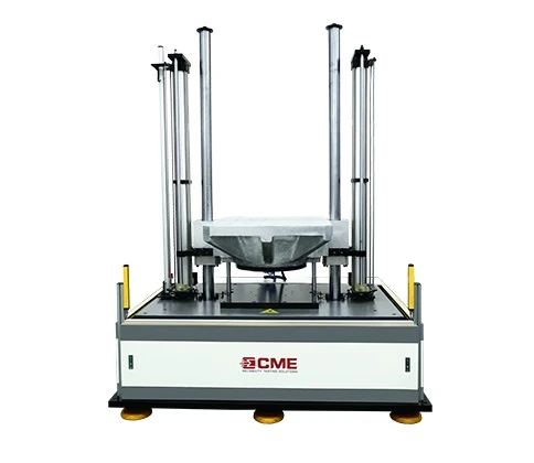
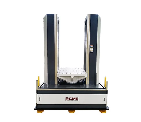
We can provide kinds of lithium battery test equipment for sale, and the price of lithium ion battery testing equipment is reasonable. If you want to buy battery testing equipment, please contact us.
CME Technology Co., Ltd. was established in 2006, specializing in the research, development and manufacturing of mechanical environment and reliability test equipment, our test equipment mechanical products including shock /bump testing machine, drop tester, transportation simulation test table, hydraulic vibration shakers, multi-DOF motion simulation table, centrifugal constant acceleration tester, packaging test machine and etc.


Sign in to leave a comment.