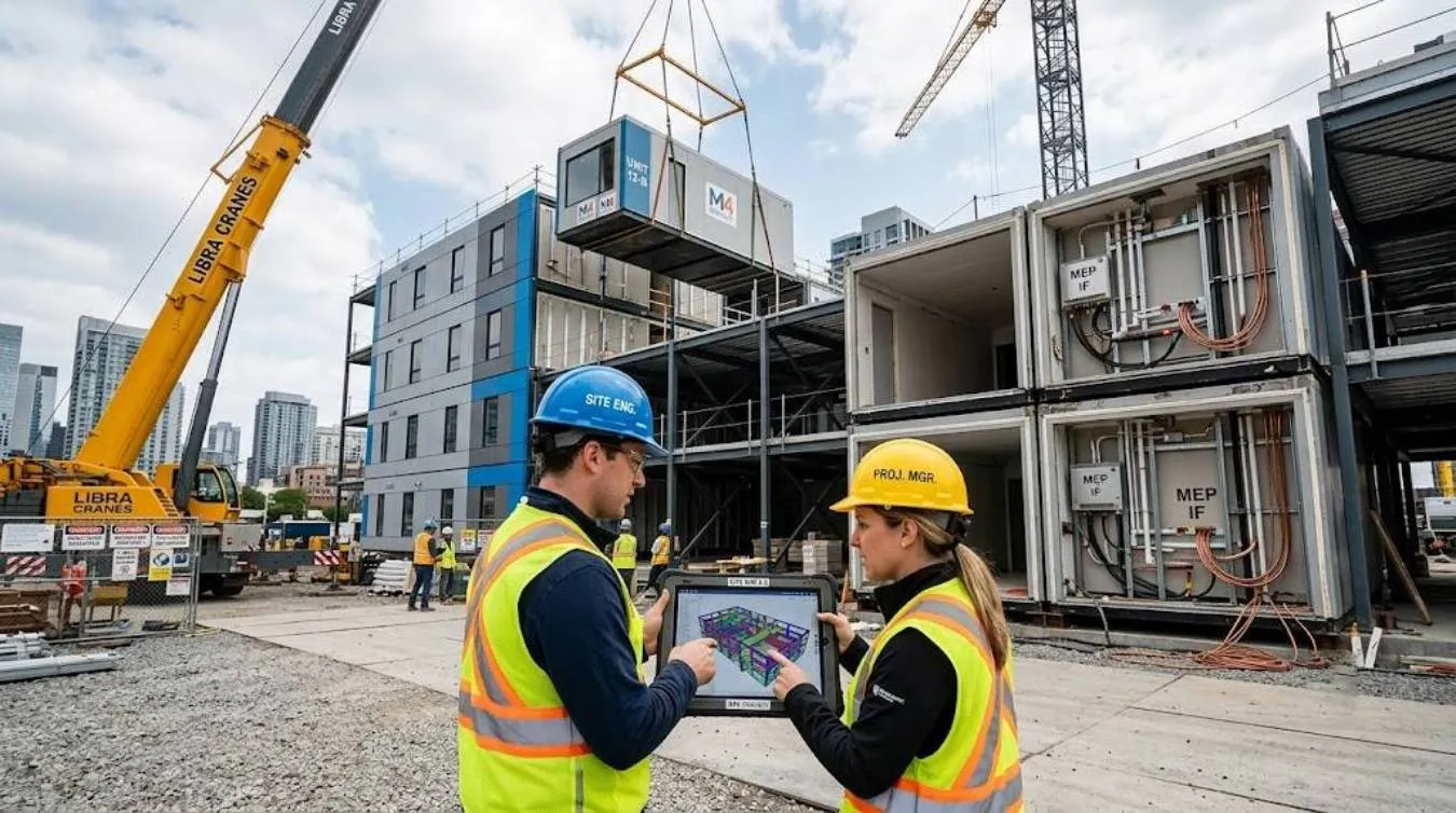

Modular construction is reshaping how the United States builds. Hospitals, multifamily housing, hotels, and schools are increasingly being delivered as factory-built modules, stacked and connected on-site in a fraction of the time required by conventional construction. But the efficiency gains that modular promises only materialize when every design discipline is working from the same coordinated digital model.
This is where Building Information Modeling becomes indispensable. A well-executed BIM coordination strategy allows design teams, manufacturers, and contractors to resolve conflicts, align tolerances, and verify system connections long before a single module leaves the factory floor. For BIM Managers, coordinators, and AEC professionals working in the modular space, the strategies below offer a practical framework for getting it right.
Why Modular Projects Demand a Higher Standard of Coordination?
In traditional construction, field crews can adapt. A pipe running two inches off-center gets rerouted. A wall that comes in slightly out of plumb gets shimmed. Those adjustments happen in real time, on-site, without anyone stopping the project.
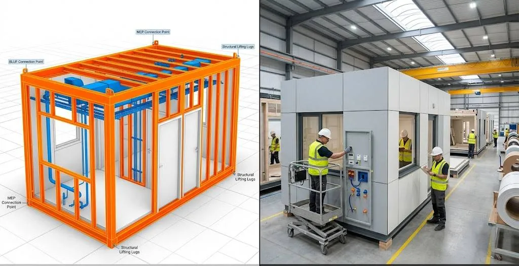
Modular construction does not offer that flexibility. Modules arrive pre-finished and pre-assembled. MEP systems are already installed inside the unit. Structural connections are pre-welded. When a conflict exists, it either went undetected in the design phase or it was caught through rigorous BIM coordination before fabrication began. There is no middle ground.
According to the Modular Building Institute, modular delivery can compress project schedules by 30 to 50 percent. Realizing that compression requires the design and coordination process to absorb the complexity that would otherwise be resolved on-site. The digital model must do the heavy lifting.
Setting Up the Project for Coordination Success
A Common Data Environment Built for Collaboration
Every successful modular BIM project begins with a well-structured Common Data Environment. The CDE is the centralized platform where all discipline models, drawings, and issue logs are stored, shared, and versioned. Platforms like Autodesk Construction Cloud, BIM 360, and Procore serve this function well in the U.S. market.
The critical requirement is that all parties, including the modular manufacturer, work within the same environment from the project's earliest stages. When each trade maintains its own folder structure or model server, coordination errors slip through the gaps between systems. A unified CDE eliminates those gaps.
Architectural and structural models developed through professional BIM modeling services should follow consistent naming conventions aligned with the National BIM Standard-United States (NBIMS-US) to ensure interoperability across the project team.
A BIM Execution Plan That Reflects Modular Realities
A BIM Execution Plan is a living project document that defines who models what, at what level of detail, and by when. For modular projects, a standard BEP is not enough. The plan must account for several modular-specific realities:
- Module boundary lines define exactly where each trade's modeling responsibility begins and ends, preventing both gaps and duplicate geometry at unit interfaces
- Level of Development milestones must tie to manufacturing release dates, not just design phases; modules cannot enter fabrication until coordination at LOD 400 is confirmed
- Fabrication tolerance standards must be embedded in the model geometry; the difference between design tolerance and factory tolerance is a coordination problem waiting to happen
- IFC and file exchange protocols must be agreed upon early so that manufacturer software and design software can communicate without data loss
How Each Discipline Contributes to a Coordinated Model?
Architecture: The Spatial Framework
The architectural model defines the spatial grid within which every other discipline operates. In modular projects, this means the architect must establish module dimensions, stack configurations, and corridor alignments with manufacturing-grade precision. Parametric families built in Revit need to reflect actual module sizes, tolerance gaps between units, and structural bearing conditions at each support point.
Professional architectural BIM services teams working on modular projects should model interior finishes, casework, and envelope assemblies to at least LOD 350, providing sufficient detail to support factory production drawings. Early coordination with the modular manufacturer is not optional; their fabrication templates and proprietary Revit families must be incorporated into the design model before detailed design begins, not after.
Structure: Two Scales of Engineering
Structural coordination on a modular project operates at two distinct levels simultaneously. At the module level, the structural model governs how individual units resist gravity loads, transport stresses, and crane lifting forces. At the building level, it addresses how stacked and linked modules behave as an integrated structural system under wind, seismic, and occupancy loads.
Structural BIM teams must model connection hardware, lifting attachments, and temporary shoring elements explicitly. These components are frequently omitted from early models because they feel like contractor scope, but they occupy real space and generate real clashes with ductwork, piping, and finished ceilings if left uncoordinated. Engaging structural BIM services professionals who understand modular-specific engineering requirements early in design significantly reduces RFIs during fabrication.
MEP: The Most Coordination-Intensive Discipline
Mechanical, electrical, and plumbing systems present the greatest coordination challenge in any modular project. Every system must be fully roughed in and often finish-installed within the module before stacking, yet each system must connect precisely to its counterpart in the adjacent module at the unit interface.
Teams delivering MEP BIM services must coordinate all duct routing, pipe runs, conduit paths, and data cabling at LOD 400 before fabrication drawings are released. This includes exact penetration locations through module walls and floors, sleeve sizes and materials, hanger locations, and seismic restraint hardware. Any ambiguity in the MEP model at the module interface becomes a field problem on installation day, and field problems in modular construction are expensive.
Clash Detection at Two Levels
Automated clash detection is the quality control mechanism that validates coordination work before fabrication begins. In modular projects, clash detection must happen at two scales: within each individual module and across the interfaces where modules connect.
Using tools like Autodesk Navisworks, the coordination team runs a federated model combining all discipline files and checks for three categories of conflict:
- Hard clashes occur when two objects physically occupy the same space, such as a structural column passing through a plumbing stack.
- Soft clashes occur when objects violate required clearance zones, such as a VAV box installed without the maintenance access its filter requires.
- Workflow clashes occur when the construction sequence creates an access problem, such as a ceiling grid installed before an above-ceiling valve can be operated.
Professional BIM clash detection services should operate on a weekly issue-and-resolve cycle during design development. Every clash is assigned to a responsible discipline with a resolution deadline. Clashes that remain unresolved past their deadline should be escalated immediately, as they represent a manufacturing release risk.
For teams configuring clash detection workflows, Autodesk's Navisworks documentation provides detailed guidance on clash rule setup, tolerance settings, and issue tracking integrations.
Coordination Through the Project Lifecycle
Early Design
Start with a module massing model that validates site coverage, zoning envelope, and stacking logic before detailed design begins. This low-LOD model aligns the full project team on spatial constraints and module counts. Changes at this stage cost almost nothing. The same change after production drawings have been released can cost weeks and significant rework fees.
Design Development Through Construction Documents
Once the module layout is frozen, discipline teams develop their models in parallel within the CDE. Coordination meetings, ideally weekly Integrated Concurrent Engineering sessions with all leads present in a shared model environment, drive clash resolution and keep all disciplines moving at the same pace.
The goal at construction document completion is a fully coordinated, clash-free federated model from which fabrication drawings can be extracted directly. This model-to-fabrication workflow is one of BIM coordination's most tangible value contributions: it eliminates the errors introduced when drafts people manually redraw coordinated designs for shop drawings.
Fabrication and Site Assembly
During fabrication, the BIM model serves as the single source of truth for the factory floor. During on-site assembly, 3D coordination views guide crane picks, module sequencing, and utility tie-in locations. As-built deviations captured during installation should be reflected in the model so the owner receives an accurate facility management asset, not a document set that diverged from reality the day modules were set.
Practical Collaboration Habits That Make Coordination Work
Technology is only part of the equation. The teams that achieve the best coordination outcomes on modular projects share several consistent habits:
- Involve the manufacturer in BIM coordination from schematic design. Their fabrication constraints should shape the design, not react to it after design development is complete.
- Use responsibility matrices. Document exactly who owns each model element. Ambiguity about ownership almost always results in either duplicated geometry or unmodeled scope.
- Bring trade contractors into the coordination environment early. Subcontractors who will perform module hook-up work on-site need to validate connection details in the model before fabrication, not after delivery.
- Confirm owner BIM deliverable requirements at project kickoff. Asset data, COBie exports, and as-built model requirements must inform how models are built from the start.
For open BIM standards that support interoperability across the modular supply chain, the buildingSMART International IFC standards provide a widely adopted framework for model data exchange between design software and manufacturer systems.
Conclusion
Modular construction puts enormous pressure on the design and coordination process because it front-loads everything that traditional construction resolves in the field. The BIM coordination strategies outlined here, from establishing a disciplined Common Data Environment and a modular-specific BEP, to coordinating architecture, structure, and MEP systems with manufacturing precision and running systematic clash detection at both the module and interface level, are what allow modular projects to deliver on their schedule and quality promises.
For BIM Managers and coordinators working in this space, the investment in rigorous upfront coordination is not overhead. It is the product. The factory runs on the model. Get the model right, and everything else follows.

























Sign in to leave a comment.