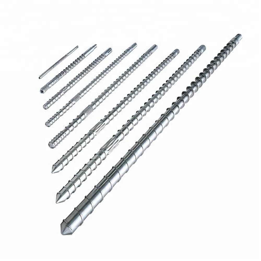
The plastic extrusion basic screw design includes three parts. These three parts are engineered to do their own specific tasks. The feed section is in the rear end of the screw. In this section the pellets of plastic are fed from above and then mover further. The length to diameter ratio of this section is five to one. This ratio is sufficient for building the pressure to transport the plastic. The plastic and the barrel wall cause friction. The friction is greater between the screw and the plastic. This happens because of the lateral movement of the material.
The heater of the barrel will develop tack and would stick to a wall. The crew is chilled and cooled to free it from the sticky pellets. The length of feed section results in more time to heat to a high temperature. It creates more friction at the barrel. After that, the plastic is moved to the transition section of the screw.
The second section is transition screw. In this section, the plastic is converted into liquid state. The barrel heater will provide temperature of initial melting. The shear will be caused by the motion of plastic against the barrel. The root of the screw increases while the flutes decrease in size.
The metering section is the next section in the screw. The melted plastic is guided to the die. The diameter and size remain constant at this stage.


Sign in to leave a comment.