How to Test a Metal Oxide Varistor?
When it comes to mov varistor testing, there are a few simple steps to follow. Firstly, ensure you have the necessary equipment, such as a multimeter and a power source. Disconnect the MOV from the circuit and check for any damage or signs of wear on the MOV core. Next, hook up the multimeter in parallel with the MOV, ensuring the correct polarity. Apply a gradual voltage to the MOV using the power source and monitor the multimeter for any changes in resistance. If the MOV conducts and allows current to pass, it is functioning properly. Remember, it is always recommended to refer to the specific guidelines provided by the metal oxide varistor manufacturer for accurate testing procedures. Testing MOVs is crucial to ensure reliable performance and protection from voltage surges for devices, power systems, and
How to Check Metal Oxide Varistor by Multimeter?
If you are wondering how to test mov varistor with multimeter, we have got you covered. The process involves a few simple steps. First, ensure the power supply to the MOV is disconnected. Set your multimeter to the resistance mode, typically indicated by the ohm symbol (Ω). Connect the multimeter leads to the terminals of the MOV. A functioning MOV should display a very high resistance reading on the multimeter. If the resistance is extremely low or close to zero, it indicates a short-circuited or damaged MOV that needs to be replaced. Checking MOVs using a multimeter is a quick and effective way to assess their functionality and ensure the protection of your electronics from voltage surges.
For IEC60099-4 Standard
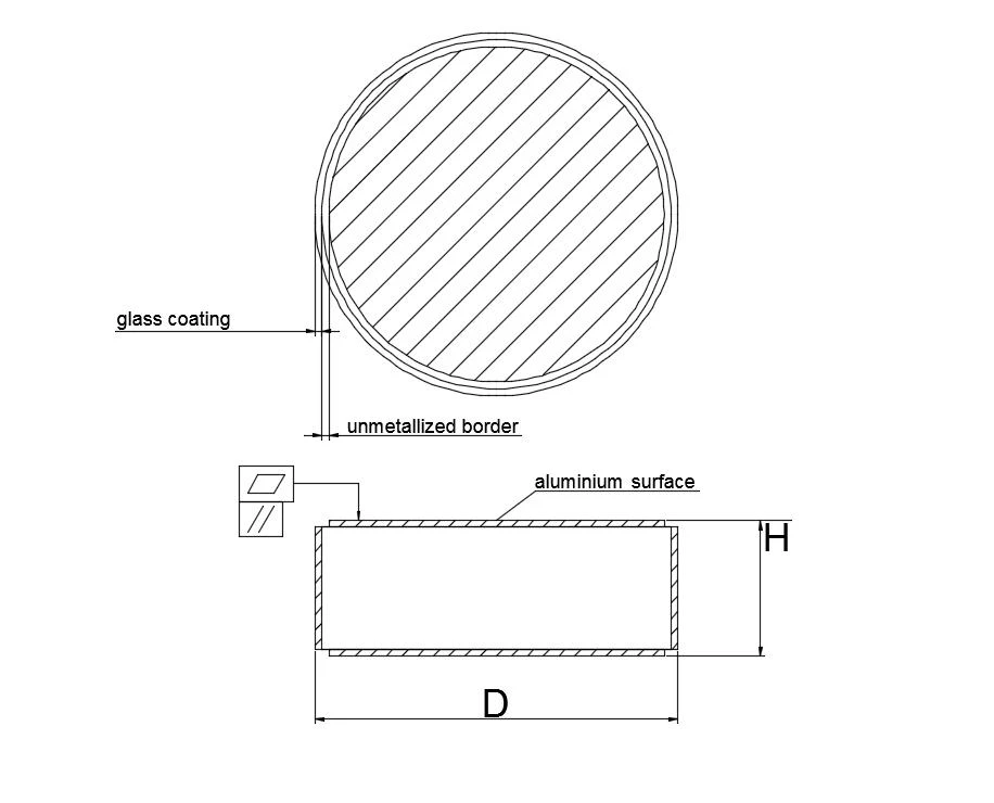
1.1 D.C. Reference Voltage Test U1mA; Sample #: (A1~A10)
1.2 Leakage Current Test IL at 0.75 U1mA; Sample #: (A1~A10)
1.3 Discharge Voltage Test IR 10kA at 8/20µs; Sample #: (A1~A10)
1.4 2000µs Rectangular Wave Impulse Current Withstand Test; Sample #: (A1~A5)
1.5 High Current Impulse Withstand Test; Sample #: (A6~ A10)
1.6 Accelerated Aging Test
1.7 Each Block Passed Two Times 2000μs Impulse Withstand Test
1.8 Power loss Test: Each Block Conducts power loss test; Sample #: (A1~A10)
The test is under 115C, 0.90* Uref and N2 or dry air. Perform 1000h test for type test and 200h test for lot
Requirements: power loss shows permanent decreasing trend or be stable after initial decreasing.Samples for type test: 3pcs
Samples for lot test: 2pcs per lot
Criterion: Both parts pass the test
3.7 Partial discharge test
Partial discharge < 2 pC at 1.05*Ures/3.0, test procedure according to lEC60099-4.
3.7 Partial discharge test
Partial discharge < 2 pC at 1.05*Ures/3.O, test procedure according to lEC60099-4.
4. U~ ICharacteristics for Information
Typical U~I curve of D71H21.4HG is illstrated as below diagram.100A to 500A are with 30/60us and 1kA to20kA are with 8/20us.
If you want to know more about metal oxide varistor failure, please visit our website.
As a metal oxide varistor manufacturer, we will do our best to meet all the needs of customers.


Sign in to leave a comment.