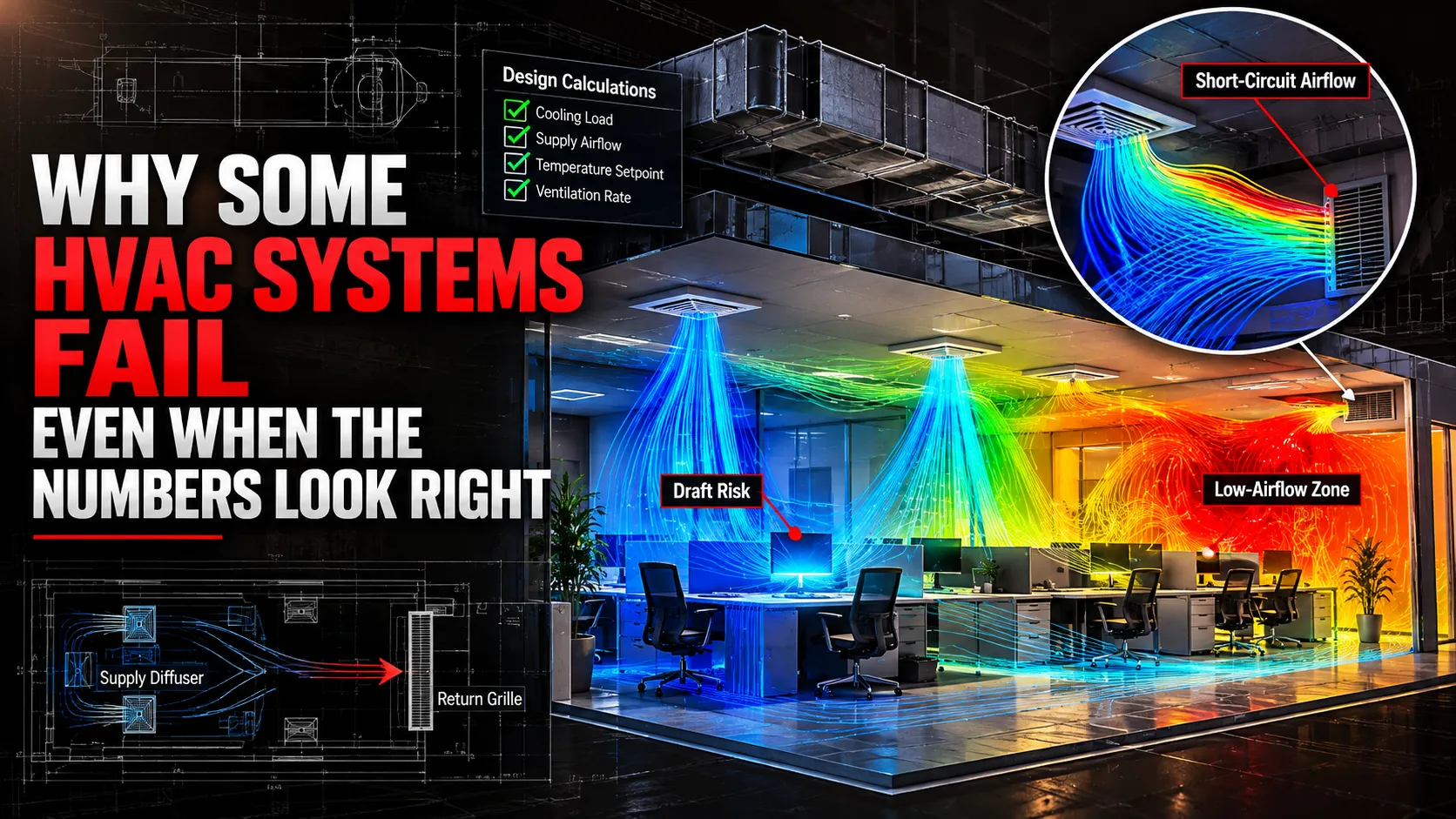


An HVAC system can meet its calculated cooling or heating load and still leave people uncomfortable.
One part of a room may feel too warm while another feels unusually cold. Supply air may move directly toward a return without properly circulating through the occupied zone. Heat from equipment may accumulate in one corner. A diffuser that looks correctly positioned on a drawing may create an unexpected draft once the system is operating.
Traditional HVAC calculations are extremely important, but they usually tell engineers how much heating or cooling a space requires. They do not always show exactly how air moves through every part of that space.
That is where Computational Fluid Dynamics services can provide another layer of engineering insight. HVAC CFD can model airflow, temperature distribution, heat transfer, recirculation, ventilation behavior, and thermal conditions throughout a defined environment before physical changes are made.
A Room Can Meet the Target Temperature and Still Feel Wrong
Imagine a large office where the thermostat shows the expected temperature.
On paper, everything looks fine.
But people sitting near one diffuser complain that the air is too strong, while another part of the room feels warmer and stagnant.
The average room temperature does not necessarily reveal either problem.
Airflow inside buildings is spatial. Air moves around walls, furniture, equipment, partitions, occupants, diffusers, returns, and openings. Different locations can therefore experience very different velocities and temperatures even when the overall HVAC system appears to be operating correctly.
HVAC CFD helps engineers visualize these differences. The analysis can show supply-air distribution, return-air behavior, recirculation zones, limited-airflow regions, interactions between supply and exhaust, and potential short-circuiting between supply and return paths.
Instead of asking only, “Is enough air being supplied?”, engineers can start asking a more useful question:
Where is that air actually going?
Airflow Distribution Is Only Half the Story

Air velocity is important, but thermal comfort is not determined by airflow alone.
Temperature distribution can vary significantly across large or complicated spaces.
Heat from machinery, lighting, occupants, solar gain, electronic equipment, or surrounding surfaces can create local temperature differences. Warm air may rise and create stratification. Cooling may concentrate in one region while another receives insufficient conditioned air.
A thermal CFD model can help investigate hot spots, cold spots, temperature gradients, stratification, heat accumulation, and interactions between conditioned and unconditioned air.
This becomes especially valuable in spaces where using one average temperature would hide what is actually happening.
A data centre, for example, may have an acceptable average room temperature while individual racks experience very different inlet conditions.
A warehouse may be comfortable near floor level but much warmer higher in the space.
A cleanroom may need more than adequate cooling. It may also require carefully controlled airflow behavior.
The engineering value comes from seeing these conditions spatially rather than relying only on one overall number.
Thermal Comfort Goes Beyond Reaching a Setpoint
One of the most useful applications of HVAC CFD is thermal comfort analysis.
A room reaching 23°C does not automatically mean every occupant experiences the same comfort.
Someone sitting directly beneath a strong supply jet may experience excessive air movement. Another person several metres away may experience low airflow and higher local temperatures.
CFD can help examine occupant-level conditions, including local air velocity, temperature differences, excessive cooling or heating, poor distribution, and areas outside intended comfort conditions. Where appropriate project inputs and criteria are available, the analysis can also support more detailed thermal comfort evaluation.
This is particularly important when the engineering question is not simply:
“Can the HVAC system cool the building?”
but instead:
“Will the occupied zones actually experience the conditions we intended?”
Where HVAC CFD Becomes Especially Valuable
Not every building needs CFD.
For simple rooms with predictable airflow, established layouts, and no significant comfort concerns, standard HVAC calculations may provide enough information.
CFD becomes more valuable when the flow behavior itself is part of the engineering problem.
Data centres are a clear example. High heat loads, tightly packed equipment, rack-level airflow, supply and return pathways, and recirculation can create conditions that are difficult to understand from system-level calculations alone. CFD can help identify hot spots and evaluate how cooling air reaches heat-generating equipment.
Cleanrooms present another challenge because airflow behavior is central to maintaining controlled environmental conditions.
Large open-plan offices, terminals, warehouses, and commercial spaces may develop uneven temperature and velocity distributions because of their size and geometry.
Industrial facilities can introduce additional complexity through equipment heat loads, process emissions, large enclosures, and complicated ventilation arrangements.
CFD can also support natural ventilation studies by examining how air enters, moves through, and exits a building under defined environmental conditions.
The point is not to use CFD simply because sophisticated simulation software is available.
The analysis should answer an engineering question that simplified methods cannot adequately answer.
Good CFD Starts With the Right Geometry
A simulation is only as useful as the model built to represent the actual system.
For HVAC applications, that process may start with architectural drawings, BIM models, CAD geometry, room dimensions, HVAC layouts, diffuser locations, returns, openings, partitions, and major heat-generating equipment.

Not every geometric detail needs to be included.
The challenge is determining which details materially influence the airflow and thermal behavior being studied.
Too little detail can remove important physical effects.
Too much unnecessary detail can create a complicated computational model without improving the engineering answer.
This is why CFD modelling is not simply a matter of importing a BIM file and pressing “solve.”
The model needs engineering judgement before the solver even begins.
Boundary Conditions Can Make or Break the Analysis

Once the geometry is prepared, the next major question is what operating conditions the model should represent.
These can include supply airflow, supply temperature, return conditions, occupancy, equipment heat loads, lighting, solar gains, wall temperatures, outdoor conditions, material properties, and ventilation rates.
These inputs matter enormously.
A beautifully rendered airflow plot based on unrealistic operating conditions does not become useful simply because the visualization looks convincing.
The simulation must represent the scenario the engineering team actually wants to investigate.
That might be a normal operating condition, a peak summer case, a high equipment-load scenario, a revised diffuser layout, or a comparison between design alternatives.
The purpose should always be clear before the computational model is built.
Mesh Where the Airflow Changes
After the geometry and boundary conditions are defined, the space is divided into computational cells.
This mesh determines how the solver represents the flow domain.
Important regions often require more resolution, particularly around supply diffusers, returns, equipment, occupied zones, narrow passages, sharp geometric changes, and areas where strong thermal or velocity gradients are expected.
A coarse mesh may fail to represent important local behavior.
An unnecessarily fine mesh everywhere can increase computational requirements without improving the decision.
As with FEA, good CFD modelling is about putting detail where the physics requires it.
The Real Value Comes After the Solver Finishes

CFD results can be visually impressive.
Velocity vectors, streamlines, pressure contours, and temperature maps can immediately attract attention.
But colorful images are not the final objective.
The purpose is to understand what those results mean for the HVAC design.
Typical outputs may include velocity contours, airflow vectors, streamlines, temperature fields, pressure distribution, thermal gradients, occupant-zone conditions, and project-specific comfort metrics.
The engineering team can then ask practical questions.
Should a diffuser be repositioned?
Is supply airflow reaching the intended occupied zone?
Is hot air recirculating?
Does the return location create short-circuiting?
Would a different airflow rate improve distribution?
Does equipment placement contribute to a local hot spot?
These are the decisions that make simulation useful.
Choose an HVAC CFD Partner for Engineering Insight, Not Just Software
Many engineering firms can access CFD software.
The more important question is how the simulation will be applied.
Different environments require different modelling decisions. Data centres, cleanrooms, commercial buildings, industrial facilities, HVAC equipment, and naturally ventilated spaces do not present identical challenges.
An experienced CFD partner should understand the physical problem, determine suitable boundary conditions, select appropriate modelling methods, refine the mesh where needed, perform relevant quality checks, and explain the results in engineering terms.
Converge ES notes that validation can include approaches such as mesh refinement, sensitivity studies, and comparison with available measurements where appropriate.
The software matters.
But the assumptions, methodology, interpretation, and recommendations matter more.
See the Air Before Building Around It
Airflow is invisible in the real world.
CFD makes it visible.
It allows engineers to examine where conditioned air travels, where heat accumulates, where recirculation develops, and where occupants or equipment may experience conditions different from the overall design target.
For complex HVAC environments, this insight can be valuable before installation, construction, testing, or expensive physical modification.
Converge Engineering Services provides CFD simulation and analysis services covering HVAC and thermal comfort, thermal flow, internal and external flow, and other engineering applications. Converge can support projects from geometry and boundary-condition definition through meshing, simulation, engineering interpretation, and reporting, helping design teams evaluate airflow and thermal behavior before committing to physical changes.





















Sign in to leave a comment.