Summary
Along with the rapid improvement of China's economic level, elevators have long come into people's lives and become a basic tool to be used every day.
This article provides a set of elevator display control solution based on Stone-STVC070WT screen, including: outside the cabin display control, inside the cabin display control, control terminal three parts, you can also use it as an advertising player to use. Uart display
Achieved functions
(A) Outside the cabin display control
Outside the cabin display panel, showing the floor where the elevator is located.Outside the cabin summoning control panel, the user completes the selection of up and down floors to summon the elevator.
(B) Inside the cabin display control
Inside the cabin display control panel, completing floor selection, opening, closing and alarming.Inside the cabin advertising panel, completing the playback of video or audio advertising.
(C) Display control of control cabinet
The control cabinet setting panel, completing elevator settings, such as stopping or starting operation, certain floors without stopping.
(D) Elevator integrated control unit
The basic logic of the integrated control unit of the elevator, in order to complete the operation control of the whole elevator system.
System principle and composition
(A) System Principle
Elevator is a large electromechanical product composed of mechanical and electrical close contact, mainly composed of machine room, shaft, cabin, door system and electrical control system.
The basic principles are:
(1) The system summons the elevator to the corresponding floor according to the summoning command (up and down command) outside the cabin, and opens the cabin door after the leveling proofreading system confirms that there is no error.
(2) The external summoning and internal door opening and closing commands can control the opening and closing of the cabin door.
(3) The floor selection command inside the cabin can control the floor to be reached.
(4) When arriving at the set floor, open the door after leveling and checking.
(5) Press the alarm bell when there is an unexpected situation during operation. Graphic LCD
(6) The billboard inside the cabin plays or pauses according to the instruction of the display control system (no announcement is broadcast when it is not moving);
(7) The control cabinet sets the panel, which can control whether the whole elevator is running and which floors are not available.
(B) System Composition
The system is mainly composed of four parts: outside the cabin display control, inside the cabin display control, display control of control cabinet, elevator integrated control unit. This article mainly completes the display control part inside and outside the cabin.
Outside the cabin display control
can be further divided into: "elevator floor display unit" and "elevator summon unit".
Inside the cabin display control
Mainly completing the functions of current floor display, floor selection & cancellation, door opening and closing, alarm, etc.
Display control of control cabinet (Show in the next article)
It can control whether the whole elevator is running, which floors are not available, get the current elevator position, continuous running time, elevator load condition; temperature and humidity information inside the elevator; smoke alarm system; condition of lighting system, etc.
Elevator integrated control unit
The operation control center of elevator, generally use PLC to realize the control of the whole elevator's electric distribution, power, fire, lighting, etc. This article in order to cooperate with the display control unit to demonstrate the program of MCU to illustrate.
System hardware design
(A) Outside the cabin display control
Hardware design of "floor display unit of elevator"Using the HMI screen of Beijing STONE Technology Co., Ltd, the module is STVC070WT-01, which integrates TFT display and touch controller.
(1) STVC070WT-01 product features:
-Controlled by any MCU.
-Displaying pictures/text/curves.
-65536 color TFT display.
-with/without touch screen.
-RS232/RS485/TTL UART interface and USB port.
-Wide voltage range.
(2) Interfaces
-Power supply interface.
DC power supply from 5V 1A power adapter.
-Communication interface
Communication with the elevator's integrated control unit via RS232 serial port to receive the sent floor and operation status information (rise, fall, stop) at a baud rate of 9600bps.
Hardware design of the "elevator summoning unit"
(1) Display control hardware
The same 7-inch Stone HMI STVC070WT-01, with a TTL UART interface to communicate with it, and the baud rate set to 9600bps.
(2) Interface
-Power supply interface.
DC power supply provided by 5V 1A power adapter.
-Communication interface
Sending current floor and up/down information to the integrated control unit via RS232 serial port with baud rate of 9600bps.
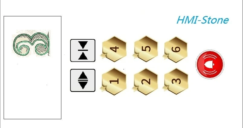
(B) Inside the cabin display control
Display control panel inside the cabinUse the 7-inch screen of STVC070WT-01, with touch function, to complete the display of floor selection, door opening, door closing, alarm and other functions.
The power supply is provided by 5V 1A power adapter, and the communication interface is RS232 serial port.
Advertising panel inside the cabin (detailed introduction in the next article)As above, connecting external speakers through the audio output interface of the HMI screen.
The power supply is adopted by 5V 1.5A power adapter, and the communication interface adopts audio interface.
(C) Analog integrated control unit
Hardware CompositionThe control circuit uses the C8051F340 as the core chip board.
The development board comes with keys to simulate the elevator running status and send corresponding commands to the inside and outside display control unit developed by Stone HMI through RS232 serial port.
Main Controller ChipThe C8051F340 device is a fully integrated mixed-signal system-on-a-chip MCU.
-High-speed, pipelined architecture with 8051-compatible microcontroller cores (up to 48 MIPS).
-Full-speed, non-intrusive on-system debug interface (on-chip)
-Universal Serial Bus (USB) capable controller with 8 flexible endpoint pipelines, integrated transceiver and 1K FIFO RAM.
-Power supply regulator.
-True 10-bit 200 ksps single-ended/differential ADC with analog multiplexer.
-On-chip voltage references and and temperature sensors.
-On-chip voltage comparators (two).
-precision-calibrated 12 MHz internal oscillator and 4x clock multiplier.
-Up to 64KB of on-chip FLASH memory.
-Up to 4352 bytes of on-chip RAM (256+4KB)
- Hardware-implemented SMBus/ I2C, enhanced UART (up to two) and enhanced SPI serial interfaces.
- four general-purpose 16-bit timers.
- Up to 40 port I/Os (5V tolerant inputs).
System software design
(A)Outside the cabin display control
Software design of "floor display unit of elevator"
(1) The development process of HMI
Firstly, create the project and load the required pictures into the project. Here we make a background picture to display the floor and upward and downward information through Ico. LCD screen manufacturers
Second, use the TOOL-2019 controls to create, dynamically associated relationships; the main controls are: "Animated icon", "Varialbe icon";
Third, software simulation and compilation to generate executable files.
Fourth, connect the HMI screen to the PC side through debugging tools and download the executable file to the screen.
(2) Software design of the analog control terminal
The software of the simulation end is used to simulate the operation status of the elevator through "+", "-", "up", "down" and "stop" buttons, and send the corresponding commands to the HMI screen.
Elevator arrives at the 1st floor: A5 5A 05 82 00 05 00 00.
Elevator arrives at the 2nd floor: A5 5A 05 82 00 05 00 01.
Elevator arrives at the 3rd floor: A5 5A 05 82 00 05 00 02.
Elevator arrival on the 4th floor: A5 5A 05 82 00 05 00 03.
Elevator arrival on the 5th floor: A5 5A 05 82 00 05 00 04.
Elevator arrival on the 6th floor: A5 5A 05 82 00 05 00 05.
/*******************************************************/
void GUI_Key_Execute(void)
{
switch(KeyValue)
{
//--Standby mode
case Key_ADD_Short:
{//--1-1:ADD button is pressed;
if(LouCeng<6)
{
LouCeng++;
}
CMD_LouCeng[7]=LouCeng;
Uart0_SendCommand(CMD_LouCeng,8);
}
break;
case Key_SUB_Short:
{//--1-1:SUB button is pressed;
if(LouCeng>0)
{
LouCeng--;
}
CMD[7]=LouCeng;
Uart0_SendCommand(CMD_LouCeng,8);
}
break;
case Key_Up_Short:
{//--1-1:UP button is pressed;
Uart0_SendCommand(CMD_ShangXing,8);
}
break;
case Key_Down_Short:
{//--1-1:SUB button is pressed;
if(LouCeng>0)
{
LouCeng--;
}
CMD[7]=LouCeng;
Uart0_SendCommand(CMD_XiaXing,8);
}
break;
case Key_Ting_Short:
{//--1-1:SUB button is pressed;
CMD_ShangXing[7]=0;
Uart0_SendCommand(CMD_ShangXing,7);
CMD_XiaXing[7]=0;
Uart0_SendCommand(CMD_XiaXing,7);
}
break;
//--Standby mode
default:break;
}
}
/******************************************************/
Software design for "elevator summoning unit"
It is relatively simple to send commands to the control port after displaying the upward and downward touch of the console, the commands are as follows.
Elevator up command: A5 5A 06 83 00 01 01 00 00.
Elevator down command: A5 5A 06 83 00 02 01 00 00.
The function of MCU emulation port is mainly to handle the serial port to receive commands.
/*******************************************************/
void Uart0_ISR(void) interrupt 4
{
//--Receiving interruptions
u8 tmp;
if(RI0)
{
RI0 = 0;
tmp = SBUF0;
//-Determine if a data message is being received
if(right_com_type)
{
Packet_Rx_Buffer_Uart0[Packet_Current_Order_Uart0++] = tmp;
//--Received data length < set length of the packet
if(Uart0_Current_Order == 8)
{
//--Determine if end of packet && checksum is correct
if(tmp == Uart0_Packet_Tail)
{
Packet_Valid_Flag_Uart0 = 1; //--Received valid packet
}
Packet_Valid_Flag_Uart0 = 0; //--No longer in receive packet state
Packet_Current_Order_Uart0 = 0; //--Clear the serial number
}
}
//-Determine if it is a packet header
else if(tmp==Packet_Header_Uart0)
{
right_com_type = 1;
Packet_Rx_Buffer_Uart0[0] = tmp;
Packet_Current_Order_Uart0 ++;
}
}
//--Sending interrupt
else if(TI0)
{
TI0 = 0;
}
}
Main函数中
if(Uart0_Packet_Flag)
{
Uart0_Packet_Flag=0;
switch(Uart0_RX_Buf[2])
{
//--Up
case 0x05:
//--Light up the light 1
break;
case 0x06:
//--Light up the light 2
break;
default:break;
}
}
(B)Inside the cabin display control
HMI-Stone uses controls such as "Varialbe icon", "Button Key value return", "increamental adjustment", "Text clock", "Animation icon" and audio properties of the controls in order to realize the function of inside the cabin display control.
(1) Software design of HMI
First of all, make the base map and do the corresponding action effect map for opening and closing the door and alarm, as shown in the following figure.
Figure 11
Place the "Button Key value return" control at the corresponding location and set its Button effect property to Figure 11, so that when the touch action occurs, the interface at the location covered by the control will display the content of Figure 11 to achieve the effect of a key press.
To create the effect of floor selection, use the "Varialbe icon" control and select the image source of the two icons, as shown in the figure below. Then the "increamental adjustment" control is used to cycle through the two images and send the corresponding commands through the serial port.
1st floor selected command: A5 5A 06 83 00 11 01 00 01.
1st floor unchecked command: A5 5A 06 83 00 11 01 00 00.
The same "Varialbe icon" control is used to create the upward and downward elevator effects, but in a way that overlaps the two controls; each control selects the image source of three icons, as shown in the figure below.
Each first one is blank, when going up, control 1 will display 3 pictures in a cycle to simulate the dynamic effect, at this time control 2 shows empty pictures; when going down, control 2 will display 3 pictures in a cycle to simulate the dynamic effect, at this time control 1 shows empty pictures.
(2) Software design of the simulation control
The software for testing the simulation terminal simulates the operation status of the elevator through the "+", "-", "up", "down" and "stop" buttons, and sends the corresponding commands to the HMI screen.
Up command start: A5 5A 05 82 00 09 00 01.
Up command stop: A5 5A 05 82 00 09 00 00.
Downstream command start: A5 5A 05 82 00 0E 00 01.
Downstream instruction stop: A5 5A 05 82 00 0E 00 00.
MCU emulation port functions, mainly to handle serial port receive commands.


Sign in to leave a comment.