Today we will explain the ATS (Auto Transfer Switch), which means the automatic transfer switch:
The function of the ATS:
It converts automatically between the general electrical supply to the feeding through electrical generators such as (diesel - gasoline).
It is used in generators with a three-phase output, and it can be used with single-phase and after
Make simple modifications to the electrical panel, which is used in residential buildings and shops.
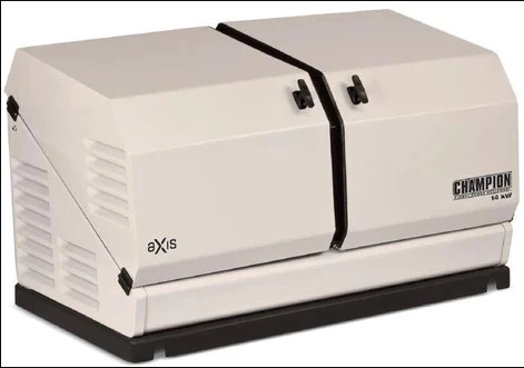
The Champion Power Equipment 100838 Home Standby Generator System includes 14kW aXis Home Standby Generator and 100A aXis ATS Whole House Automatic Transfer Switch.
The way of work :
It is a selector key that chooses one of two systems, either a manual or an automatic system.
Explanation of the Manual System:
It consists of 4 Push Buttons, two of them are divided into one to operate the electrical transformer and the other to operate the general current
The other two are divided into one to turn off the electrical transformer and the other to turn off the general current, and it can be replaced by the 4 Push Button
The selector is used with three degrees divided into one to operate the transformer, the other to operate the general current, and the third to turn off
The transformer and the main current together.
Explanation of the automatic system:
Here, the conversion process is done automatically. In the normal case, the loads are fed from the general current. In the event of a general power outage or
Irregularity is separated and connected to the generator to carry out the process of feeding the loads, you must notice two points:
The electric generator is connected to the loads in the event of disconnection or irregularity of the general current again.
The generator is connected and disconnected after a certain time in the event of a general disconnection.
Components of the ATS control circuit:
2 contactors of the same type and current for the supply sources and mechanical protection that can be installed on them
Load Protection MCCB Breaker Number
Three timers of the on-delay type are equipped to work all the time
1 over and under voltage relay device and another phase sequence and failure relay
1 automatic battery charger to charge the battery, and its charging current must be suitable for the battery and have overheat protection the current
2 relays
Four indicator lights, two green and two red
3-position selector switch to switch between manual and automatic
Two keys of type NC push buttons and two keys of type NO push buttons
Plus some other components.
There is Km which is a contactor for the general current.
There is Kg which is a contractor for the electric generator.
There is also an O - U Voltage Relay:
It is placed parallel to the electric generator to ensure the value of the potential difference outside the generator.
Ph - S Relay is also available:
It performs its function by making sure of the general electrical current and its regularity, in the event of an interruption
Or an irregular condition that sends a signal for the conversion process to the generator current.
There is also the MCCB:
It is the so-called moulded case circuit breaker, it is connected before pregnancy to protect it from high electrical current or the occurrence of
Short Circuit in both cases.
Now let's study how the generator works:
This part is very important, and I want to focus on it:
After the generator works, sure, not the first time it starts, a regular voltage will come out, but after how many seconds, and the voltage from the generator is regularized, a device will perform
OU Voltage, i.e. over and under voltage relay, closes its open point connected to a relay coil named K2.
The relay closes its open point K2 connected to the selector key S1, which is in position 1 (ie, automatic) for that.
The timer file T3 will work and after the time set on it this timer (about 10 seconds and depends on the power of the generator, its type and
Also on the load capacity) it will close its open point T3 and will run the contactor Kg file and the generator will be inserted and fed
pregnancy to.
As for the general current:
When the general current returns and is regular, the phase sequence and failure relay device will close its open point and turn on
Relay file K1 This relay does the following
He opens its closed point connected to the generator operating terminals and then disconnects it.
It closes its connecting point with the selector switch S1 (which is in position 1) and activates the T1 and T2 tamarins.
The timer T1 is set to a time lower than T2
The timer T1, after the set time has elapsed, disconnects the Kg contactor, that is, disconnects the generator feed
The timer T2, after the set time has elapsed, turns on the contactor coil Km and thus enters the general current feed.


Sign in to leave a comment.