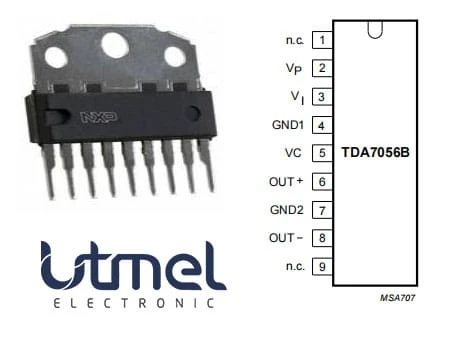
Hi! Hope you have a wonderful day! Today I would like to have a discussion on TDA7056B Audio Amplifiers. The TDA7056B is a DC volume-controlled mono Bridge-Tied Load (BTL) output amplifier. This article mainly introduces schematic, pinout, datasheet and other detailed information about NXP Semiconductors TDA7056B.
DescriptionThe TDA7056B is a mono Bridge-Tied Load (BTL) output amplifier with DC volume control. It's designed for use in televisions and monitors, but it may also be utilized in portable recorders and radios that run on batteries. The device is placed in a 9-pin medium-power box.
There is also an MCL (Missing Current Limiter) incorporated. The MCL circuit is activated when the current differential between the output terminals of each amplifier surpasses 100 mA. (300 mA typ). This current level of 100 mA is appropriate for usage with headphones (single-ended).
2. CAD Model
The followings are the Symbol, Footprint of TDA7056B.
Symbol
Footprint
3. Features
• DC Volume Control
• Few External Components
• Mute Mode
• Thermal Protection
• Short-circuit Proof
• No Switch-on and Switch-off Clicks
• Good Overall Stability
• Low Power Consumption
• Low HF Radiation
• ESD Protected on All Pins
4. Functional Block Diagram
5. TDA7056A VS TDA7056B
TDA7056A and TDA7056B differ in a few electrical parameters, but their core functions are identical, and they can be used interchangeably. This IC provides volume control, overheating protection, short-circuit protection, and expansion functions in addition to the 3.5WBTL power amplifier circuit. It features a wide operating voltage range (4.5-18V), a small number of external components, and stable performance.
6. Simplified Schematic
TDA7056A and TDA7056B are two TDA7056 variants that have been more frequently available in recent years. Despite the fact that their performance and pinout are very similar, they cannot be used in the same circuit.
The TDA7056B appears to be the superior of the two, with an output power somewhat greater than 16 ohms and, this time, a datasheet reference power output of 5.5W for an 8-ohm speaker. This is the only chip I brought and tested because it appears to be the best.
TDA7056A/TDA7056B require at least two more parts than TDA7056. Because a DC volume control input must be grounded via a 1F capacitor, this is the case. The input pins of the TDA7056A/TDA7056B (as opposed to the TDA7056) have a DC offset, necessitating the insertion of a 470nF capacitor in series with the input and input pins.
As a result, there are some disadvantages, such as the need for more components and larger circuit boards. The advantage is that with the DC volume control pin 5 we have greater freedom than with the standard TDA7056:
The volume control potentiometer can now be connected to this dedicated pin.
The accuracy of a logarithmic potentiometer is higher than that of a logarithmic volume control input. Ordinary linear potentiometers can now be used to control loudness.
This is a schematic diagram of a simple amplifier after tweaks. The maximum gain of the TDA7056A is roughly 27dB, while the maximum gain of the TDA7056B is around 32dB.
Simplified Schematic
Power supply bypass capacitors: C1 and C2 are required, just like the TDA7056. C1 should be 100nF ceramic and as close to the TDA7056B pin as possible. C2 is a 220F or greater electrolytic capacitor. Because electrolytic capacitors are polarized, the positive lead must be connected to a source of positive voltage. This is the longest lead if the capacitor is brand new, but check the case nevertheless because the negative lead is generally plainly indicated.
The input capacitance is C3. The data sheet recommends using 470nF in combination with a 20k input impedance to get a high-pass cutoff frequency of 16.93Hz (calculated by 1/(2RC)-1/(2*3.14159*20000*0.00000047).
Polyester or electrolytic capacitors should be used in place of C3. Polyester fiber offers the best audio quality, but on an amplifier this size, you won't notice the difference, so electrolyte will suffice. Ceramic capacitors should never be used. Please feel free to use 1µF electrolyte if you have any (this is what I did on the circuit board). Face the chip with the positive lead.
R1 gives the audio signal a grounded DC route as well as a predictable input impedance for the amplifier, making it ideal for any source you connect. The data sheet recommends a 5k resistor, however 4.7k is a more widely accessible amount that will perform just as well.
7. Applications
• TV and Monitors
• Battery-fed Portable Recorders
• Radios
8. Package
That is all for today. Hope this article is helpful to you.


Sign in to leave a comment.