
Key Takeaways
- Industrial control panel symbols and colors help operators understand machine status quickly and safely.
- Standardized labeling based on IEC 60617 and NEMA panel labeling improves consistency and reduces errors.
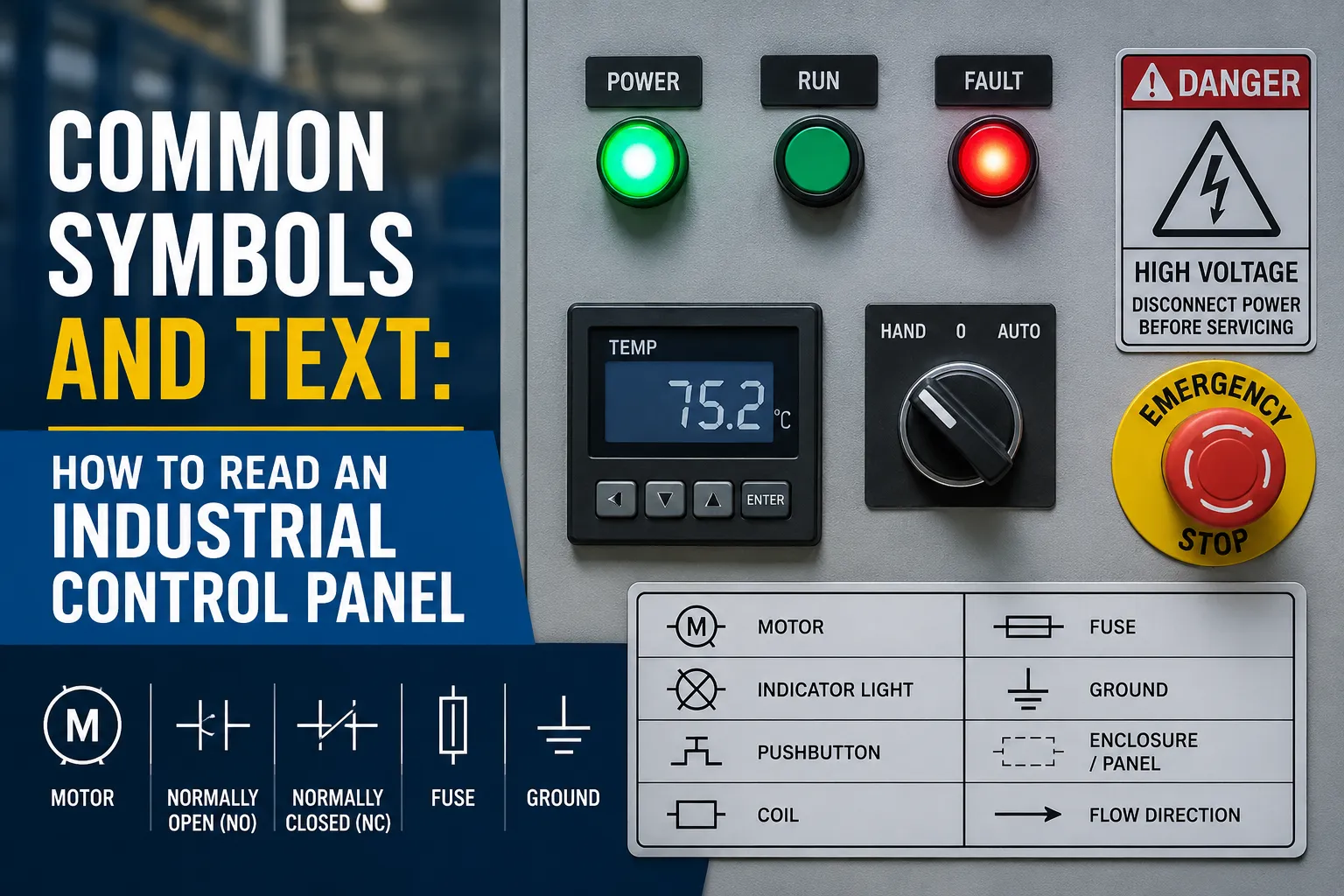
- Pilot device color codes follow a universal logic: Red for danger, Yellow for warning, and Green for normal operation.
- Legend plates, tags, and abbreviations provide clear functional identification for operators and maintenance teams.
- Proper panel organization and consistent labeling improve troubleshooting, safety, and operational efficiency.
Introduction: The Language of the Control Face
An industrial control panel is more than a collection of buttons, switches, and lights—it is the communication center between the machine and the operator.
Every symbol, label, and color on the panel face is designed to communicate important information quickly and clearly. In industrial environments where speed and accuracy matter, operators must understand machine conditions instantly without hesitation.
This is why standardization plays such a critical role in modern panel design. Universal symbols based on standards like IEC 60617 and consistent pilot device color codes help eliminate confusion, reduce reaction time, and overcome language barriers in global manufacturing environments.
For engineers and maintenance personnel, understanding industrial control panel symbols is essential not only for operation but also for troubleshooting and safety.
The Hierarchy of Pilot Device Colors
One of the easiest ways to understand a control panel is through color recognition. Most panels follow a logical color hierarchy similar to traffic signals.
Red: Emergency or Stop Conditions
Red is universally associated with danger, emergency stop conditions, or faults.
Examples include:
- Emergency stop push buttons
- Fault indicator lights
- Stop commands
Because of its urgency, red is typically reserved for conditions requiring immediate attention.
Yellow or Amber: Warning Conditions
Yellow indicates abnormal conditions or situations requiring caution.
It is commonly used for:
- Warning indicators
- Overload conditions
- Maintenance alerts
Yellow tells the operator that the system is still functioning but requires attention.
Green: Safe or Normal Operation
Green is associated with safe operating conditions.
Typical uses include:
- Start buttons
- Running indicators
- System ready status
A green pilot light usually means the process is operating normally.
Blue, White, Grey, and Black
Blue often represents mandatory actions, such as a reset function.
White, grey, and black are generally used for standard operational controls that do not carry specific safety meaning.
Understanding these pilot device color codes helps operators identify machine conditions quickly, even from a distance.
Deciphering Universal Symbols (ISO/IEC Standards)
Modern control panels rely heavily on standardized symbols to maintain consistency across industries and countries.
Power Symbols
One of the most common examples is the binary logic notation:
- “I” = ON or Start
- “O” = OFF or Stop
These symbols are internationally recognized and widely used on switches and power controls.
Another common symbol is the standby icon, which indicates that the system is not fully disconnected but is in a low-power or logic-enabled state.
Understanding the difference between a hard disconnect and standby condition is important during maintenance and troubleshooting.
Directional and Motion Symbols
Arrows are commonly used to indicate:
- Rotation direction
- Conveyor movement
- Jog functions
- Cycle operations
Clockwise and counter-clockwise symbols are especially common in motor control applications.
Emergency Stop Symbols
Emergency stop devices follow strict identification rules.
Typically, they feature:
- Red mushroom-head push buttons
- Yellow background plates for visibility
This contrast helps operators locate the E-stop quickly during emergencies.
These conventions are critical for compliance with industrial safety standards and NEMA panel labeling requirements.
Reading the Text: Legend Plates and Tags
While symbols provide quick recognition, text labels provide detailed function identification.
For example:
- “Conveyor 1 Start”
- “Main Pump Stop”
- “Cooling Fan Reset”
These labels remove ambiguity and help operators interact with the correct equipment.
Common Panel Abbreviations
Industrial panels often use shorthand terms to save space.
Some common examples include:
- AUTO/MAN = Automatic or Manual mode
- FWD/REV = Forward or Reverse
- ESTOP = Emergency Stop
- ACK = Alarm Acknowledge
Understanding these abbreviations is essential for operators and maintenance personnel.
Dual-Language and Icon-Based Labeling
As manufacturing becomes more global, many facilities now use bilingual labels or icon-only interfaces.
This approach improves communication across multilingual workforces and supports international machine exports.
In some cases, symbols alone are preferred because they eliminate translation inconsistencies entirely.
Component-Level Identification
Understanding individual device behavior is another important part of reading a control panel.
Pilot Lights vs. Illuminated Push Buttons
A pilot light only indicates system status.
For example:
- Green light = Motor running
- Red light = Fault condition
An illuminated push button, however, combines operator control with visual feedback.
This distinction helps operators understand both the system condition and the device state.
Selector Switches
Selector switches often include visual indicators showing operating positions.
Examples include:
- Hand/Off/Auto
- Local/Remote
- Forward/Reverse
Some switches remain in position after operation (“maintained”), while others automatically return to center (“spring return”).
Proper visual marking helps operators understand how the switch behaves before use.
The Role of Nameplates
External nameplates provide important maintenance and safety information such as:
- Voltage ratings
- SCCR (Short Circuit Current Rating)
- UL or NEMA ratings
These markings are critical during servicing, upgrades, and fault analysis.
Understanding the difference between reading electrical schematics vs. panel faces is important here. Schematics explain internal electrical logic, while the panel face communicates operational interaction.
System Logic: Putting It All Together
Good control panel design is not just about labeling individual components—it’s about organizing information logically.
Devices performing related functions are usually grouped together.
For example:
- A Start button may sit beside its Running indicator light
- A selector switch may appear next to its fault reset button
This physical arrangement helps operators understand machine relationships quickly.
Consistency is equally important.
Facilities should maintain the same visual vocabulary across all panels. When every panel uses identical symbols, colors, and labeling conventions, operator training becomes easier and the risk of human error decreases significantly.
This is one reason why companies prioritize standardized c3controls operator identification systems and consistent panel design practices.
Conclusion: Engineering Clarity
A well-designed control panel communicates clearly, quickly, and safely.
From industrial control panel symbols and color conventions to standardized text and grouping logic, every detail contributes to safer operation and faster troubleshooting.
For operators, this means fewer mistakes and quicker response times.
For engineers and OEMs, it reflects a professionally engineered system built around clarity, safety, and reliability.
In industrial environments, the best control panels are not necessarily the most complex—they are the easiest to understand under pressure.























Sign in to leave a comment.