Introduction
RC circuits are widely used in analog circuits and pulse digital circuits. Use Resistor R and Capacitor C form a frequency selection network, which is an RC oscillator circuit. The oscillation circuit is an amplifying circuit with no input but outputs AC signal. Of course it needs DC power supply. Therefore, its function is to convert DC power into AC power. Here you have questions. What is the reason for the oscillation of the RC circuit? What are the RC Oscillation Circuit types?
RC Circuit Configuration
Understand the cause of RC circuit oscillation. First we must know understand the basic composition of it and its main function. It generally consists of an amplifying circuit, a feedback circuit, a frequency selection network and a stabilizing part.
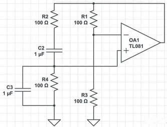
Fig 1. RC Oscillation Circuit
1) Amplifying Circuit
The amplifying circuit in the RC oscillator circuit has an integrated operational amplifier. It can amplify the signal. What’s more, the amplifying circuit and the feedback network form a positive feedback network. It has an important practical role in the RC oscillator circuit.
2) Feedback Network
In the RC oscillator circuit, connect the integrated operational amplifier and the RC series circuit. And connect a wire to the positive terminal of the integrated op amp at the junction of the RC series circuit and the RC parallel circuit. At this time, you can get a feedback network connected as a positive one.
3) Frequency-Selective Network
The frequency-selective network of the RC oscillator circuit is an RC-RC series-parallel circuit network. And it is composed of resistors and capacitors.
Causes of RC Circuit Oscillation
Pure RC circuit can oscillate. This oscillation is the same as the LC circuit. If there is no external energy input, it is not sustainable. Because resistance will continue to consume energy. The reason for the oscillation of the RC circuit is due to the mechanism of capacitor discharge. When the capacitor is fully charged, the energy is all in it. And there is no current in the circuit. When the capacitor discharging, the current in the circuit reaches its peak value. At this time, all the energy is present in the circuit in the form of current. Of course, in this process, the resistor will consume the energy in the circuit proportionally. In fact, it becomes the internal energy. Since the voltage & current steady states do not overlap, the circuit can’t work stably. So the process of charging-discharging will repeat continuously. In this process, the energy loss on each resistor during charge-discharge process decreases exponentially.
In theory, RC circuit with amplifier can achieve permanent oscillation. Because the amplifier (no matter DC or AC) is an external energy input component.
Classification
1) RC Series Circuit
Fig 2. RC Series Circuit
Let’s talk the characteristics of the circuit. Due to the presence of capacitors that cannot flow DC current. Both resistor and capacitor have an blocking effect on the current. The resistance and capacitive reactance determine the total impedance. And it changes with frequency. RC series have a turning frequency: f0=1/2πR1C1. In addition, it is basically unchanged when the input signal frequency is greater than f0, which is equal to R1.
2) RC Parallel Circuit
Fig 3. RC Parallel Circuit
The RC parallel circuit can pass both DC and AC signals. It has the same turning frequency as the RC series circuit. When the input signal frequency is less than f0, the signal relative to the circuit is DC. And the total impedance of the circuit is equal to R1. When the input signal frequency is greater than f0, the capacitive reactance of C1 is relatively small. In addition, the total impedance is the sum of resistance value and the capacitance. When the frequency is high to a certain level, the total impedance is zero.
3) RC Series-Parallel Circuit
Fig 4. RC Series-Parallel Circuit
There are two turning frequencies f01 and f02 in the RC series-parallel circuit:
f01=1/2πR2C1, f02=1/2πC1*[R1*R2/(R1+R2)]
(1)When the signal frequency is lower than f01, C1 is equivalent to an open circuit, and the total impedance of the circuit is R1+R2.
(2)When the signal frequency is higher than f02, C1 is equivalent to a short circuit, and the total impedance of the circuit is R1 at this time.
(3)When the signal frequency is higher than f01 and lower than f02, the total impedance of the circuit changes from R1+R2 to R1.
4) Summery
The RC series-parallel network oscillator circuit generates low-frequency sine wave signals. And it is a widely used RC oscillator circuit from. For the common RC oscillator circuit, switching the frequency band (coarse frequency adjustment) often use the high-stability capacitor. And then use the double variable potentiometer to fine-tune the frequency.
The RC series-parallel sine wave oscillator circuit composed of an op amp does not rely on the transistor inside. But enter the nonlinear region to stabilize the amplitude. Achieve the purpose of amplitude stabilization by introducing negative feedback from the outside.
Common Types
1) RC Phase Shift Oscillator
It has the advantages of simple circuit, less cost and easy operation. But the frequency selection effect is poor. Because the amplitude is not stable, the frequency adjustment is inconvenient. Therefore, it is suitable for occasions with fixed frequency and low stability requirements. Its oscillation frequency is: fo=1/(2πRC).
2) RC Bridge Oscillator
Combine the RC series-parallel frequency selection networks and the amplifier to form an RC oscillator circuit. In addition, the amplifier part can use an integrated operational amplifier.


Sign in to leave a comment.