
The design of injection molding gates relates to factors like part size, shape, mold structure, injection process conditions, and part performance. However, regarding its basic function, the gate cross-section should be small and its length short. This is because only then can it meet requirements such as increasing flow velocity, achieving rapid cooling and sealing, facilitating part separation, and minimizing gate marks.
Gate Location Must Meet Five Requirements
- Appearance requirements (ejector marks, weld lines).
- Product functional requirements.
- Mold machining requirements.
- Part warpage and deformation.
- Ease of gate removal.
Impact on Production and Function
- Flow Length
Flow length determines injection pressure, clamping force, and whether the part fills completely. Shortening the flow length can reduce injection pressure and clamping force. - Gate Location
Gate location affects packing pressure, its magnitude, and its balance. Place the gate away from areas subject to force (like bearing points) to avoid residual stress. Gate location must consider venting to avoid air traps. Do not place the gate at weak points or areas with inserts in the part to avoid deflection.
Techniques for Selecting Gate Location
1. Gate
A gate is a short channel with a small cross-sectional area. It connects the runner to the mold cavity. The purpose of a small cross-sectional area is to achieve the following effects:
(1) The gate freezes soon after cavity filling.
(2) Runner removal is simple.
(3) After removal, only minor marks are left.
(4) Filling control is easier for multi-cavity molds.
(5) Overfilling is reduced.
2. Gate Location and Size
(1) Place the gate at the thickest section of the part. Feeding from the thickest area provides better filling and packing. If packing is insufficient, thinner sections solidify faster than thicker ones. Avoid placing gates where thickness changes suddenly. This prevents hesitation or short shots.
(2) If possible, feed from the center of the part. A central gate provides equal flow lengths. Flow length affects required injection pressure. Central gating ensures uniform packing pressure in all directions. This avoids uneven volumetric shrinkage.
(3) As melt flows into the runner, the plastic near the mold wall cools and solidifies first. Subsequent flow occurs over this solidified layer. Plastic is a poor heat conductor. This solid layer acts as insulation, allowing the inner melt to keep flowing.
Therefore, ideally, the gate should be placed at the side of the runner. This creates the best plastic flow effect. This is most common with round or hexagonal runners. However, trapezoidal runners cannot achieve this. The gate cannot be placed at their side middle position.
When deciding gate location, follow these principles:
(1) Melt should fill all cavity sections as evenly as possible.
(2) During injection, the flow front should be stable and consistent.
(3) Consider potential issues: weld lines, air bubbles, sinks, short shots, jetting.
(4) Facilitate easy, preferably automatic, runner removal.
(5) Gate location should coordinate with all aspects.
There are no strict rules for gate design. It's often based on experience. But two basic factors require compromise:
(1) Larger gate cross-section and shorter length are better. This reduces pressure loss.
(2) The gate must be narrow for quick freezing and to prevent excessive backflow. Therefore, the gate is at the runner side. Its cross-section should ideally be circular. However, the gate shape is usually determined by the part shape.
3. Gate Size
Gate size is determined by its cross-sectional area and length. The following factors decide the optimal gate size:
(1) Material flow properties.
(2) Part wall thickness.
(3) Amount of melt injected into the cavity.
(4) Melt temperature.
(5) Mold temperature.
Gate Balancing
If a balanced runner system cannot be achieved, the following gate balancing methods can be used to reach the goal. This method is suitable for molds with many cavities.
There are two gate balancing methods:
- Changing the length of the gate channel.
- Changing the cross-sectional area of the gate.
In another scenario, when cavities have different projected areas, gates also need balancing.
In this case, to determine gate sizes, first decide the size of one gate. Calculate the ratio between this gate and its corresponding cavity volume. Then apply this ratio to compare other gates with their corresponding cavities. This determines the sizes of the other gates. After actual trial injections, the gate balancing operation can be completed.
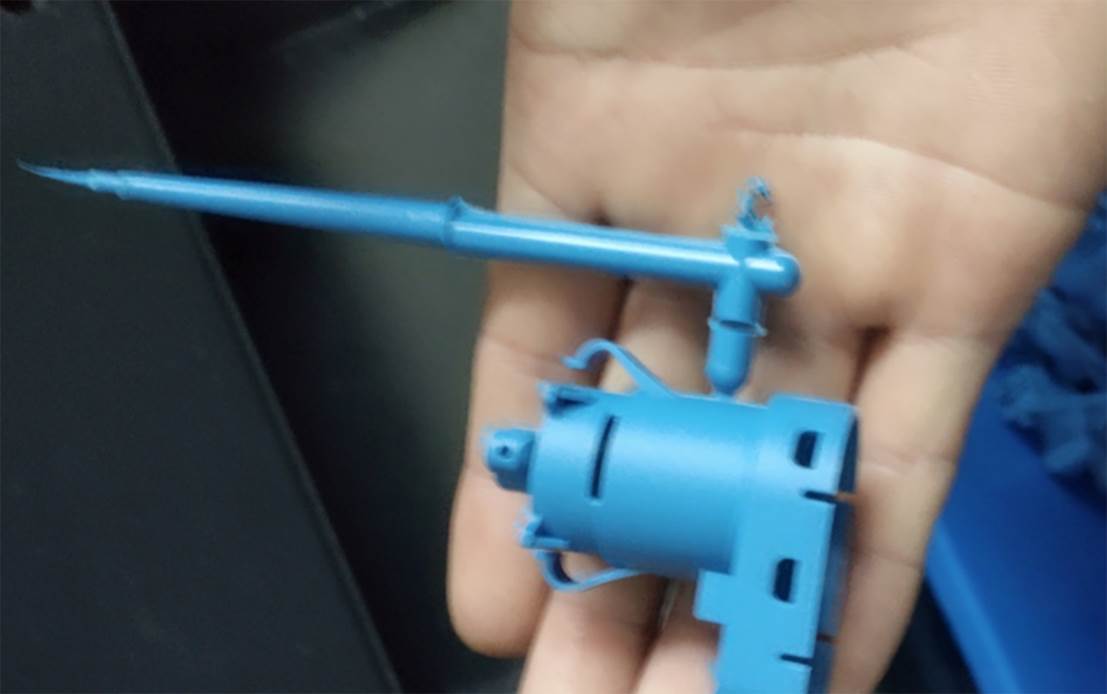
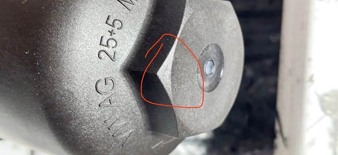
Direct Gate or Sprue Gate
The sprue supplies plastic directly to the finished part. The sprue remains attached to the part. In two-plate molds, a sprue gate is typically one per part. Sprue gates are rarely used in three-plate mold or hot runner mold designs.
Disadvantage: Leaves a sprue mark on the part surface, affecting its appearance.
Gate Selection
The gate is the connection between the runner and the cavity. It is the final part of the injection mold feeding system. Its basic functions are:
- Allow the melt from the runner to enter and fill the cavity as quickly as possible.
- After cavity filling, the gate should cool and seal rapidly. This prevents uncooled plastic in the cavity from flowing back.


Sign in to leave a comment.