
What are MEP permit drawings?
MEP permit drawings are the mechanical, electrical, and plumbing drawings submitted as part of a building permit application. They show plan reviewers that the building's mechanical (HVAC), electrical (panels, circuits, lighting), and plumbing (fixtures, pipes, drains) systems comply with applicable codes including the International Mechanical Code (IMC), National Electrical Code (NEC/NFPA 70), and International Plumbing Code (IPC). MEP permit drawings are reviewed by building department plan reviewers before a permit is issued, and construction cannot legally begin until the permit is approved.
Introduction
Most project managers and developers can read an architectural floor plan. They can follow an elevation drawing. They understand what a site plan shows.
MEP permit drawings are different. The symbols are specialized. The schedules contain technical abbreviations. The single-line electrical diagram looks nothing like the physical layout of the building. And the plumbing riser diagram shows the system vertically in a way that doesn't obviously correspond to any floor in the building.
The result: many project managers and developers review MEP permit drawings by checking whether they look complete how many sheets are there, does there appear to be something for each discipline without being able to evaluate whether the content is actually correct, code-compliant, or consistent with the rest of the permit package.
This guide provides a practical framework for reading and reviewing MEP permit drawings not at the engineering level, but at the project management level where understanding what you're looking at matters for schedule, budget, and risk management.
Section 1: Reading Mechanical (HVAC) Permit Drawings
What to Look For
Equipment schedule - the first thing to find in a mechanical permit package is the equipment schedule. This is a table listing every major HVAC unit: air handling units, rooftop units, exhaust fans, VAV boxes. Each piece of equipment has a tag (AHU-1, RTU-2, EF-3), its location, its capacity in tons or CFM, its electrical requirements, and connection sizes.
The equipment schedule tells you whether the HVAC design is sized for the building. If the schedule is sparse only showing one piece of equipment for a large floor plate that's a signal worth flagging with the mechanical engineer.
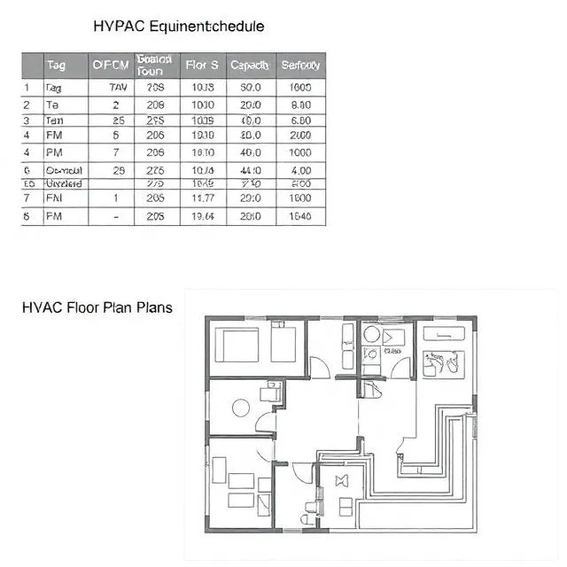
Floor plan layouts - the HVAC floor plans show where equipment is located and how ductwork is routed through each floor. Key things to check at a non-engineer level:
- Does every occupied area of the building have ductwork serving it? If there are rooms on the floor plan that don't have any supply or return air shown, that's a problem.
- Is there a mechanical room shown? Large equipment needs a room. If there's no mechanical room on the floor plan, ask where the equipment is going.
- Do the duct routes seem physically possible given the ceiling heights shown on the architectural drawings?
Energy compliance forms - HVAC permit packages must include documentation showing the mechanical system meets the applicable energy code (ASHRAE 90.1 or jurisdiction specific). These are typically calculation sheets or compliance forms, not drawings. If they're missing from the permit package, that's a common reason for permit review comments.
Section 2: Reading Electrical Permit Drawings
The Single-Line Diagram
The most important and most confusing element of an electrical permit package is the single-line diagram (SLD). It shows the electrical system schematically from the utility service entrance through distribution equipment to branch circuits. It's called a "single-line" because each circuit is shown as a single line regardless of how many actual conductors it contains.
What to read in an SLD at a project management level:
Service entrance - the leftmost or topmost element, showing where power comes in from the utility, the service size (in amps and voltage), and the main disconnect.
Distribution panels - the boxes labeled "MDP" (main distribution panel), "DP" (distribution panel), or "MSB" (main switchboard) show how power flows from the service entrance to individual panels throughout the building.
Panel schedules - each electrical panel on the project has a panel schedule showing every circuit in that panel: the circuit breaker size, the load connected to it, and the load calculation. A complete permit package has a panel schedule for every panel shown on the SLD.
Project managers can check: Are panel schedules present for every panel shown on the single-line diagram? If the SLD shows six panels and only three panel schedules are in the package, that's incomplete.
Electrical Floor Plans
Electrical floor plans show lighting fixtures, switches, receptacles, and equipment connections at each floor level. Key checks:
- Does every room have lighting shown?
- Are exit signs and emergency lighting shown at required locations (exit doors, exit pathways, stairs)?
- Is there electrical shown for all mechanical equipment on the HVAC drawings? (Every piece of HVAC equipment needs a power connection)
Section 3: Reading Plumbing Permit Drawings
The Riser Diagram
The plumbing riser diagram shows the entire plumbing system vertically - not as it's laid out on a floor plan, but showing how pipes connect from the point of connection at the ground level through each floor to the roof. It's essentially the plumbing system "unfolded" into a vertical schematic.
A complete plumbing riser diagram shows:
- Water service entry point and meter location
- Hot and cold water distribution from main to each floor
- Drain, waste, and vent (DWV) system from fixtures down to the building drain and out to the sewer
- Pipe sizes at each branch and riser
- All fixture connection points labeled by fixture type
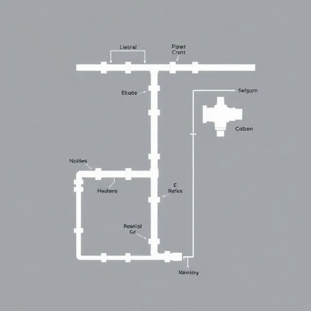
What project managers can check: Does the riser diagram show connections to all floors in the building? If the building has five floors but the riser only shows three, that's a gap worth flagging.
Plumbing Floor Plans
Plumbing floor plans show fixture locations sinks, toilets, floor drains, equipment connections and the pipe routing serving them. Check that plumbing is shown in every bathroom, kitchen, and wet area on the architectural floor plan.
Fixture schedule - a table listing every plumbing fixture: type, flow rate, connection sizes, and ADA-compliance designation. Every accessible restroom must have ADA-compliant fixtures the fixture schedule should indicate this.
Section 4: What Inconsistencies Between MEP and Architectural Drawings Look Like
The most common permit review comments on MEP drawings don't involve MEP errors in isolation they involve inconsistencies between MEP drawings and the architectural permit drawings submitted simultaneously.
Equipment not on both sets: An air handling unit shown on the mechanical floor plan that doesn't appear anywhere on the architectural floor plan. Plan reviewers compare the two.
Room names that don't match: The mechanical drawing calls a room "Mechanical Room 101." The architectural drawing calls the same room "Storage 101." This inconsistency creates confusion and sometimes triggers a reviewer comment.
Missing coordination at penetrations: Every MEP pipe or duct that penetrates a fire-rated wall or floor must be shown with a fire-rated sleeve or damper. If the architectural drawings show fire-rated assemblies at locations where MEP penetrations occur, but the MEP drawings don't show the corresponding dampers or sleeves, that's a coordination gap that generates review comments.
These inconsistencies are typically not fundamental design problems they're documentation coordination failures that are straightforward to correct. But each correction requires a revised drawing and a review cycle that adds 3–6 weeks to the permitting timeline.
MEPF design and drafting services that produce MEP permit drawings coordinated against the architectural permit set not developed independently eliminate most of these inconsistencies before submission.
Frequently Asked Questions
Q: Do all three MEP disciplines need to be in the permit package?
A: For most commercial occupancies, yes - mechanical, electrical, and plumbing drawings are all required as part of a complete building permit application. Some jurisdictions allow a deferred submittal process for certain systems (fire suppression is commonly deferred), but core HVAC, electrical, and plumbing must typically be in the initial submission.
Q: Who reviews MEP permit drawings at the building department?
A: Building departments typically have separate plan reviewers for mechanical, electrical, and plumbing disciplines. A permit package may be reviewed by three different specialists simultaneously, or sequentially, depending on the jurisdiction. Each reviewer focuses on code compliance within their discipline which is why cross-discipline inconsistencies can be missed in review and discovered during inspection.
Q: What is a "deferred submittal" for MEP systems?
A: A deferred submittal is a permit package element that is approved separately from the main permit typically because the detailed design depends on contractor selection or equipment specification that happens after the main permit is issued. Fire suppression systems are most commonly deferred. The main permit includes a note indicating that the fire suppression system will be submitted separately for review and approval before installation.
Q: How long does MEP permit review take?
A: MEP permit review timelines vary significantly by jurisdiction and project type. In major cities with high permit volumes, MEP review can take 6–12 weeks for commercial projects. Smaller jurisdictions may complete review in 2–4 weeks. Expedited review is available in many jurisdictions for an additional fee. First-submission approval without correction cycles is the most reliable way to minimize total permitting timeline.
Key Statistics
- MEP documentation gaps are cited in approximately 65% of commercial permit correction notices making them the leading category of permit review comment
- Average time added per correction cycle on commercial MEP permits: 3–6 weeks per round, depending on jurisdiction backlog
- Projects using coordinated MEP permit sets - where mechanical, electrical, and plumbing drawings are reviewed against each other and against architectural drawings before submission achieve first-submission approval rates of 70–85%, compared to under 40% for independently produced MEP sets
- Energy compliance documentation missing from the initial submission is the single most common standalone correction item in jurisdictions that have adopted ASHRAE 90.1 or Title 24
Conclusion
MEP permit drawings don't need to be a black box for project managers and developers. Understanding what each discipline's permit package should contain equipment schedules, floor plans, single-line diagrams, riser diagrams, energy compliance forms and knowing what inconsistencies to look for between MEP and architectural drawings gives project managers the ability to do a meaningful pre-submission review that catches the most common permit comment triggers before they cost weeks.
The permit process doesn't have to be a series of surprises. With coordinated documentation and a systematic pre-submission review, first-submission approval is achievable and the weeks saved are real schedule value.


Sign in to leave a comment.