

What is BIM Level of Development (LOD) and why do coordination failures, false positive clash detection results, and fabrication errors happen when discipline models at incompatible LOD levels are federated into a single coordination environment?
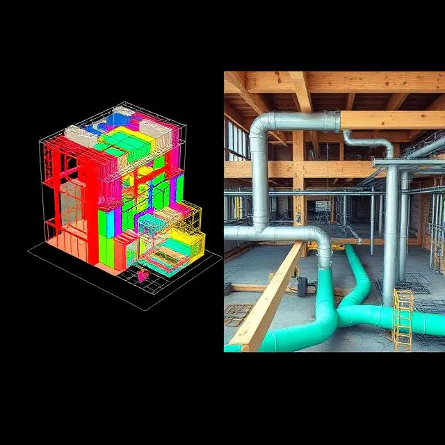
BIM Level of Development (LOD) is a standardized framework that defines how much geometric detail and how much non-graphical data a Building Information Model element must contain at each stage of a project's design and construction lifecycle ranging from LOD 100 where elements are conceptual placeholders with approximate geometry, through LOD 300 and 350 where elements have construction-accurate geometry and connection interfaces, to LOD 400 where elements carry fabrication-level detail, and LOD 500 where elements are verified to reflect as-built conditions. Coordination failures happen when discipline models federated at incompatible LOD levels are clash-detected together because the clash detection results reflect the detail level of the least-developed model in the federation a mechanical model at LOD 350 with insulation thickness and hanger geometry will generate false clashes against a structural model at LOD 200 with approximate member positions, while genuine conflicts between elements at their actual installed positions are missed because the structural model doesn't show the elements at their correct location.
Introduction
LOD is one of the most referenced standards in BIM practice and one of the most inconsistently applied. Every BIM Execution Plan references it. Every model exchange protocol specifies it. And on a significant proportion of projects, the discipline models that are federated for coordination are not at the LOD the BEP specified either because the specification was too vague to enforce, because the modeling team interpreted the LOD requirement differently from the coordination team, or because the schedule compressed the model development phase below the time required to achieve the specified LOD.
The consequences are coordination failures that appear in three forms: clash detection that produces thousands of false positives because models are at different detail levels; coordination drawing issue that approves routings that turn out to conflict with elements modeled at higher detail after coordination is complete; and fabrication errors because shop drawings were produced from a model whose geometry turned out to differ from the as-designed condition when the model was updated to coordination LOD.
Understanding exactly what each LOD requires, where the critical LOD thresholds are in the construction workflow, and what happens when those thresholds aren't met is the knowledge that makes LOD specifications enforceable rather than decorative.
What Each LOD Level Requires
LOD definitions in BIM practice follow the BIMForum LOD Specification, which is updated annually and is the most widely referenced standard in US practice. The UK and international practice uses ISO 19650's concept of Level of Information Need (LOIN), which covers similar ground with different terminology. The following covers the BIMForum LOD framework:
LOD 100 - Conceptual
At LOD 100, model elements represent the overall building massing total building footprint, approximate floor areas, approximate building height. Individual elements (walls, columns, beams) are not yet modeled as distinct objects; the building is represented by massing volumes that convey scale and area but no geometric detail.
LOD 100 is used at the earliest feasibility and schematic massing stage. It supports gross area calculations, solar analysis on building form, and massing model visualization for planning pre-application consultation. It is not sufficient for any coordination purpose.
LOD 200 - Approximate Geometry
At LOD 200, model elements are represented as generalized systems, assemblies, or components with approximate quantities, size, shape, location, and orientation. A structural column at LOD 200 is a column object at the approximate cross-section size and in the approximate location but not necessarily at the exact structural grid position, exact cross section dimensions, or with any connection geometry.
LOD 200 is used for schematic design coordination checking that the structural system fits within the architectural envelope, that MEP systems can be accommodated within the planned ceiling zones, and that the overall building organization works as a spatial proposition. It is not sufficient for construction coordination clash detection because the approximate geometry produces both false positives (clashes between elements that won't actually conflict when modeled at their correct geometry) and missed clashes (genuine conflicts between elements whose approximate positions don't reveal the conflict that their correct positions would show).
LOD 300 - Specific Geometry
At LOD 300, model elements are represented with specific geometry accurate quantity, size, shape, location, and orientation relative to the project coordinate system. A structural beam at LOD 300 is at the correct grid location, at the correct section depth and width, and at the correct elevation. The element is modeled accurately enough to produce construction drawings from it.
LOD 300 is the standard for coordinated construction documentation plans, sections, and elevations produced from the model reflect the actual design intent at the level of accuracy the documents need to convey. It is sufficient for major system coordination but not for the detailed interface coordination that LOD 350 addresses.
LOD 350 - Construction Coordination
At LOD 350, model elements include the interfaces and connections between elements the information needed to coordinate the construction of adjacent and connected components from different disciplines. A structural beam at LOD 350 shows the connection plates, the bolt groups, the cope dimensions where the beam is coped to clear an adjacent member, and the embed plates cast into adjacent concrete elements. An MEP duct at LOD 350 shows the duct lining, the insulation, the hanger and support geometry, and the access door locations.
LOD 350 is the standard for construction coordination clash detection the level of detail at which all the elements that actually occupy space in the finished building are represented in the model, so that clash detection finds conflicts between elements as they will be installed rather than between simplified representations of those elements.
BIM coordination and LOD 350 modeling services that develop discipline models to LOD 350 before federation and clash detection with connection geometry in the structural model, insulation in the MEP models, and hanger geometry in the ductwork models produce clash detection results that reflect what will actually conflict in the field, not what the simplified geometry models appear to conflict with.
LOD 400 - Fabrication
At LOD 400, model elements are represented with fabrication-level detail the geometry, tolerances, and non-graphical information needed to fabricate the element. A steel connection at LOD 400 shows every bolt hole at its exact diameter, every weld preparation at its exact geometry, and every plate at its exact cut dimensions. A precast concrete panel at LOD 400 shows every reinforcing bar at its exact position, every embed plate at its exact location, and every lifting insert at its confirmed type and position.
LOD 400 is the standard for fabrication shop drawings and is typically developed by the fabricator or specialty contractor, not by the design team or the construction coordination team. The structural engineer's LOD 350 coordination model becomes the reference from which the fabricator develops the LOD 400 shop drawing model.
LOD 500 - As-Built
At LOD 500, model elements have been verified to reflect the actual installed or constructed condition dimensions, location, and non-graphical data have been verified in the field and updated in the model to match what was actually built rather than what was designed. LOD 500 is the as-built model standard the model delivered at project handover that represents the building as it was constructed, which becomes the facility management reference for the building's operational life.
The Critical LOD Thresholds in Construction Workflow
Not all LOD transitions are equally consequential. The transitions that most commonly produce coordination failures are:
The LOD 200 to LOD 300 transition at design development
When design coordination is conducted against LOD 200 models and the design team proceeds to design development without completing the LOD 300 update, the coordination that was done at LOD 200 is based on approximate geometry. Design development decisions structural grid adjustments, MEP system selections, ceiling height determinations that were made based on LOD 200 coordination may turn out to be incompatible with the actual geometry that the LOD 300 model reveals.
The LOD 300 to LOD 350 transition at coordination
This is the most consequential LOD transition for construction coordination. A coordination model at LOD 300 doesn't show MEP insulation, structural connection plates, hanger geometry, or the access requirements for installed equipment. Clash detection at LOD 300 misses the conflicts between these elements the duct insulation that conflicts with the structural beam flange, the pipe hanger that conflicts with the structural connection plate that show up as field conflicts when these elements are installed.
The LOD 300 coordination model approves a routing. The field installs to the approved routing. The insulation contractor installs insulation and discovers the beam flange conflict. The coordination model approved a routing that works for the naked duct — it didn't check the routing for the insulated duct.
The LOD 350 to LOD 400 transition at fabrication
When fabrication shop drawings are developed from a LOD 350 coordination model, the fabricator's LOD 400 model typically reveals additional geometric detail exact bolt hole patterns, exact cut lengths, exact plate dimensions that the LOD 350 model didn't show. If this additional detail produces elements that conflict with the coordination model's approved routings, the conflict isn't caught until the shop drawing review.
Where LOD Specifications Fail in Practice
LOD Specified by Phase Without Element-Level Detail
A BIM Execution Plan that specifies "LOD 300 at design development" and "LOD 350 at construction coordination" without specifying which elements must be at which LOD, and which can remain at a lower LOD, produces a coordination environment where the overall LOD specification is met on average but specific elements the ones where LOD 300 vs LOD 350 makes the most difference are at the lower LOD.
The element-level LOD specification the LOD matrix that lists every model element category (structural columns, structural beams, MEP ductwork, plumbing pipe, electrical cable tray, etc.) and the required LOD at each project phase is the specification that makes LOD enforceable, because it allows the BIM manager to check each element category against its specification rather than assessing the overall model against a vague phase requirement.
LOD Applied to Geometry But Not to Non-Graphical Data
LOD specifications have two components: geometric LOD (what geometry must the element contain?) and information LOD (what non-graphical data attributes must the element have?). BEPs that specify geometric LOD requirements without specifying information requirements produce models where the geometry is at the required LOD but the data attributes material specifications, equipment data, fire ratings, thermal values are absent or incorrect.
For BIM uses that depend on the model's non-graphical data quantity takeoff, energy analysis, facilities management handover a model that meets the geometric LOD requirement but not the information requirement fails those uses even when it passes a geometric LOD check.
LOD Not Enforced at Model Exchange
The LOD specification has no value if it isn't enforced at the point of model exchange when discipline models are submitted to the common data environment for federation and coordination. A pre-submission model quality check that verifies each discipline model against the LOD requirements before it is accepted into the coordination environment catches LOD deficiencies before they affect the coordination results.
Without a pre-submission LOD check, models that don't meet the LOD specification enter the coordination environment, produce misleading clash detection results, and are discovered to be non-compliant only when the coordination results fail to match field conditions.
Structural detailing and BIM coordination services that apply pre-submission LOD verification checking each discipline model against the element-level LOD matrix before accepting it into the coordination environment ensure that clash detection is run against models that meet the LOD standard the coordination results depend on.
LOD by Discipline - Key Requirements
Structural models at coordination LOD (350)
- All primary members (columns, beams, braces) at actual cross-section dimensions and correct grid positions
- Connection plates, end plates, clip angles, and gusset plates at actual dimensions
- Bolt groups shown at actual diameter, spacing, and edge distance
- Cope dimensions shown where beams are coped
- Embed plates and headed studs at actual position and dimensions
- Camber shown on long-span beams affecting deck elevation
Mechanical models at coordination LOD (350)
- Ductwork at actual external dimensions including insulation thickness
- Flexible connections at equipment connections shown at actual geometry
- Duct access doors shown at actual dimensions and clearance zone
- Hanger rod and clevis at actual geometry below duct
- VAV boxes and terminal units at actual dimensions
- Equipment at actual footprint dimensions including maintenance clearance zone
Plumbing models at coordination LOD (350)
- Pipe at actual outside diameter including insulation
- Slope shown on drainage pipes minimum slope maintained throughout horizontal run
- Cleanout access zones shown
- Trap and P-trap geometry shown at fixture connections
- Pipe hanger geometry shown
Electrical models at coordination LOD (350)
- Cable tray at actual external dimensions including fill ratio allowance
- Conduit at actual outside diameter
- Panel and switchboard at actual footprint dimensions including door swing and working clearance
- Cable tray support and trapeze at actual geometry
Frequently Asked Questions
Q: What is the difference between LOD and LOG in BIM?
A: LOD (Level of Development in BIMForum terminology, or Level of Detail in some older usage) refers primarily to the geometric development of model elements how much 3D detail the element contains. LOG (Level of Geometry) and LOI (Level of Information) are terms used in the ISO 19650 framework to separately specify geometric development and information development. In practice, the most commonly referenced standard in US AEC practice is the BIMForum LOD Specification, which uses LOD 100 through LOD 500 to specify both geometric and information requirements at each level. The UK and international practice using ISO 19650 uses Level of Information Need (LOIN) as the overarching framework.
Q: Can different elements in the same model be at different LOD levels?
A: Yes - and this is the standard practice. A structural model for construction coordination will typically have primary structural members (columns, beams) at LOD 350, secondary framing at LOD 300, and miscellaneous framing at LOD 200. The LOD matrix in the BIM Execution Plan specifies the required LOD for each element category at each project phase. The coordination team needs to know which elements are at which LOD to interpret clash detection results correctly a clash between a LOD 350 duct and a LOD 200 structural member may not represent a real conflict if the structural member's position changes when it's modeled at LOD 350.
Q: How is LOD verified in a model?
A: LOD verification is performed through a combination of visual review and automated model checking. Visual review involves opening the model and inspecting representative elements against the LOD specification verifying that a structural beam shows connection plate geometry (LOD 350) rather than just the member section (LOD 300), or that MEP ductwork shows insulation (LOD 350) rather than the bare duct face (LOD 300). Automated model checking using tools like Solibri, Revit model checkers, or custom Dynamo scripts can verify that required element properties are populated and that element dimensions meet minimum detail requirements for the specified LOD.
Q: At what LOD should models be delivered to the facility management team at project handover?
A: The LOD for FM handover depends on what the FM team will use the model for. For spatial reference and asset identification locating equipment, identifying spaces, extracting room areas LOD 300 geometry with populated asset data attributes is sufficient. For maintenance access planning verifying that equipment can be accessed for servicing LOD 350 geometry that shows maintenance clearances is required. For as-built verification confirming that installed elements are at their design positions LOD 500 verification is required. The FM handover LOD requirement should be specified in the project's Asset Information Requirements (AIR) before the BIM execution plan is written, so that the LOD strategy serves the FM use case from the start.
Q: What happens if a fabricator's LOD 400 model conflicts with the coordination model?
A: When the fabricator's LOD 400 shop drawing model reveals conflicts with the coordination-approved routing the most common case being connection plate geometry that conflicts with MEP clearances the coordination model approved the conflict goes back through the coordination process: the fabricator identifies the conflict in the shop drawing submittal, the coordination team reviews it, a resolution is agreed, the coordination model is updated, and the shop drawing is revised. This process adds time and cost to the fabrication schedule that a LOD 350 coordination model with connection geometry would have prevented.
Conclusion
BIM Level of Development is the framework that makes the coordination model's results interpretable it defines what each element in the model represents, how much of the installed element's geometry is captured, and therefore what the clash detection results from that model can and cannot tell the coordination team about field conflicts.
LOD specifications that are vague, that aren't enforced at model exchange, or that aren't verified at the element level rather than the project level produce coordination models whose results mislead as much as they inform producing false positives that waste coordination meeting time and missing genuine conflicts that produce field problems. LOD specifications that are element-specific, enforced at submission, and verified against both geometric and information requirements produce coordination models whose clash detection results accurately predict what will conflict in the field and what won't.
The investment in rigorous LOD specification and enforcement is the investment in coordination results that the construction team can rely on results that identify real field conflicts, that don't drown the coordination process in false positives, and that give the fabrication team a coordination model accurate enough to develop shop drawings from without discovering new conflicts in the LOD 400 detail.




























Sign in to leave a comment.