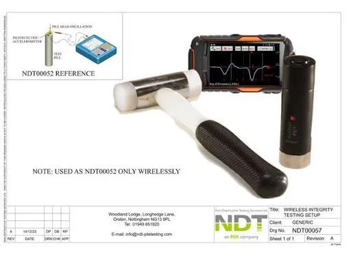

Understanding the condition of deep foundation piles is an important part of construction quality control. While conventional testing can provide valuable information about concrete integrity, advanced imaging techniques can offer engineers a more detailed view of potential variations within a pile.
3D crosshole tomography builds on crosshole sonic logging by using measurements collected from multiple access tubes to create a three-dimensional representation of the tested area. This can help engineers visualize potential anomalies and better understand their location and distribution. 🏗️

What Is Crosshole Tomography?
Crosshole tomography is an advanced approach to interpreting crosshole sonic logging data. Instead of considering measurements only along individual paths between access tubes, tomography uses multiple measurements to develop a spatial representation of the tested pile volume.
This can provide additional information about where changes in concrete response may occur.
The technique can be particularly useful when engineers need a more detailed understanding of a suspected anomaly identified during conventional crosshole testing.
Understanding CSL Tomography Equipment
Specialized CSL tomography equipment is used to collect the measurements required for advanced analysis. The equipment works with ultrasonic testing probes positioned inside access tubes installed within a deep foundation element.
Measurements are collected at different depths and between different tube combinations. These datasets can then be processed to create a more detailed representation of the tested region.
The quality of the final interpretation depends on several factors, including the quality of the field measurements, access tube configuration, testing procedures, and analysis methods.
How Crosshole Tomography Works
The basic process begins with ultrasonic measurements collected between pairs of access tubes.
Rather than relying on a single measurement path, multiple paths are used to gather information across different areas of the pile. These measurements can then be processed using specialized algorithms to estimate variations within the tested volume.
The resulting model can provide a visual representation of areas where the measured response differs from surrounding regions.
This makes crosshole tomography particularly valuable when engineers need to investigate the location and extent of potential anomalies.
3D Crosshole Imaging
One of the major advantages of this approach is the ability to create 3D crosshole imaging.
Traditional data presentation may show measurements along individual testing paths. A three-dimensional representation can provide a different perspective by displaying information spatially.
Engineers can use this visualization to better understand:
- The approximate location of potential anomalies
- The distribution of unusual measurements
- Changes across different depths
- Relationships between multiple testing paths
- Areas that may require additional investigation
The resulting image should be interpreted alongside the original testing data and project information rather than being considered independently.
3D Tomography for Pile Foundations
3D tomography for pile foundations can be particularly useful for large or complex deep foundation elements where a detailed understanding of internal conditions is required.
Large piles may contain multiple access tubes, creating an opportunity to collect measurements from numerous directions. Combining these measurements can provide more detailed spatial information than examining individual paths alone.
This can support engineering teams when evaluating unusual test results or determining whether additional investigation may be appropriate.
Advanced CSL Analysis
Advanced CSL analysis involves more than simply collecting ultrasonic measurements. The data needs to be processed and interpreted carefully to produce meaningful information.
Specialized software can help organize measurements and generate visual representations of the tested pile.
Engineers can then review the results alongside construction records, pile geometry, concrete information, and other available evidence.
This comprehensive approach can help reduce the risk of drawing conclusions from isolated measurements.
Pile Test Tomography
Pile test tomography is an extension of pile integrity assessment that focuses on creating a spatial interpretation of crosshole testing data.
It can be useful when standard CSL results indicate an area of interest but additional information about the location or distribution of the anomaly is needed.
By combining measurements from multiple paths, tomography can provide a more detailed view of the tested region.
However, the technique does not eliminate the need for engineering judgment. Results should be reviewed by qualified professionals familiar with the testing method and the project requirements.
Pile Defect Imaging
One important application of tomography is pile defect imaging.
Potential anomalies may appear as areas where the reconstructed measurements differ from surrounding regions. Depending on the circumstances, these areas could be associated with changes in concrete quality or other conditions affecting ultrasonic signal transmission.
It is important to distinguish between identifying an unusual response and determining its exact cause. Further investigation may be required before a definitive conclusion can be made.

Crosshole Imaging Software
Crosshole imaging software plays an important role in processing and displaying the information collected during testing.
Advanced software can assist with organizing measurement data, creating visualizations, and generating three-dimensional models.
A clear interface can also make it easier for testing professionals to review results and communicate findings to engineers and project stakeholders.
The software should complement professional analysis rather than replace engineering interpretation.
CSL Tomography Interpretation
Proper CSL tomography interpretation is essential for obtaining meaningful conclusions from the collected data.
Engineers should consider factors such as:
- Testing configuration
- Number and position of access tubes
- Data quality
- Signal measurements
- Pile geometry
- Construction records
- Concrete placement information
- Other available integrity testing results
A suspected anomaly should be evaluated in context rather than based solely on a single image or measurement.
Why 3D Tomography Can Be Valuable
The primary benefit of 3D tomography is improved visualization.
When multiple testing paths are combined, engineers can gain a better understanding of where a potential anomaly may be located within the tested volume.
This can help support decisions about whether additional testing, investigation, or other engineering evaluation is necessary.
For complex foundation projects, having a spatial representation can make technical data easier to communicate and review. 📊
When Should Tomography Be Considered?
Tomography may be particularly useful when conventional CSL testing identifies an area requiring further evaluation.
It can also be considered when project requirements call for more detailed visualization of foundation integrity.
The decision to use tomography should be based on the project specifications, pile configuration, testing objectives, and engineering requirements.
A qualified testing professional can help determine whether advanced analysis would add value to the investigation.
Benefits of a Three-Dimensional Approach
A three-dimensional testing approach can offer several practical advantages:
Better visualization: Potential areas of concern can be represented spatially.
Multiple measurement paths: Data from several paths can contribute to the reconstruction.
Detailed analysis: Engineers can investigate complex patterns in the testing results.
Improved communication: Visual models can make technical information easier to discuss with project teams.
Additional investigation support: Results can help identify areas that may warrant further examination.
These benefits make tomography a useful complementary technique within an overall foundation testing program.
Conclusion
3D crosshole tomography provides an advanced way to analyze and visualize information collected during crosshole sonic logging. By combining measurements from multiple testing paths, the technique can create detailed representations of potential variations within pile foundations.
From CSL tomography equipment and crosshole imaging software to advanced CSL analysis and pile defect imaging, these technologies can provide engineers with additional information when evaluating complex foundation conditions. 🔎
3D tomography for pile foundations should always be interpreted alongside original testing data, construction information, and professional engineering judgment. When used appropriately, it can provide a valuable additional perspective for understanding deep foundation integrity and supporting informed decisions about further investigation.




























Sign in to leave a comment.