Structure of a Router Antenna Protective Cover Handle
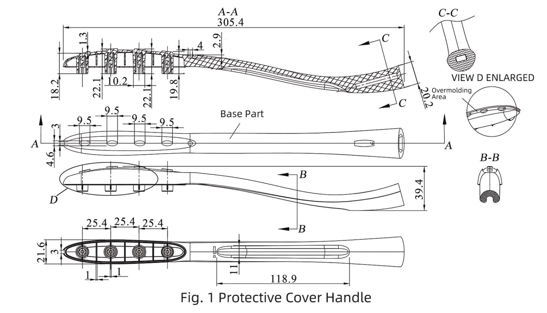
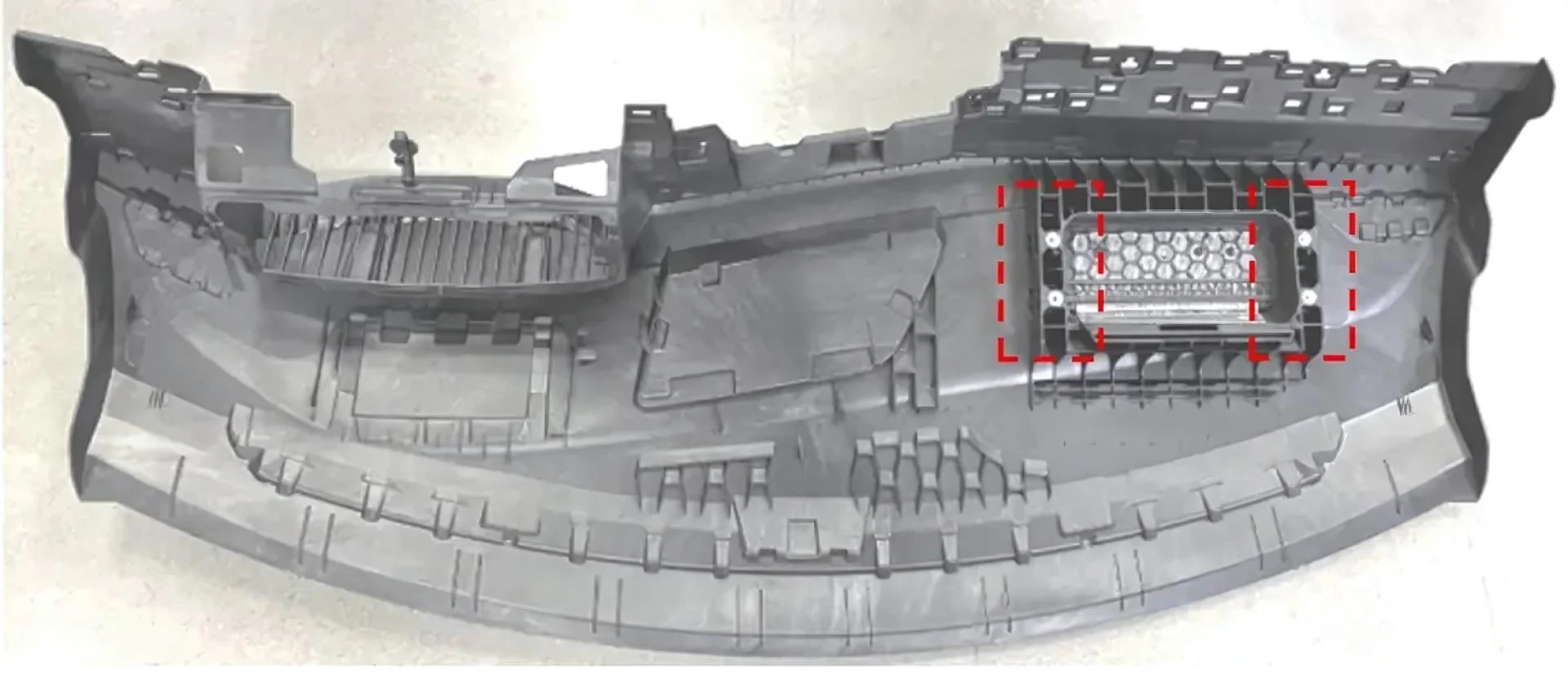
The structure of a router antenna protective cover handle is shown in Figure 1. The total production volume is 800,000 pieces. The plastic part is composed of two materials. The base part is injection molded from a blend of Polycarbonate (PC) and Acrylonitrile Butadiene Styrene (ABS), abbreviated as ABS+PC. The overmolded layer is formed by overmolding with a Thermoplastic Rubber (TPR) material. The overall dimensions of the part are 305.4mm × 21.6mm × 39.4mm. The thickness of the overmolded layer is 1.3mm. The overmolding area is located at the center of the left end face of the part. It is shaped as a long ellipse. Within this area, there are 4 bosses and 1 recessed hole. These features ensure a strong bond between the TPR overmold and the base part. At the left end of the part, there is a 3mm wide opening. This opening is used as the feed point for the overmolding material during injection. For part molding, the base part is first formed using one injection molding machine and its corresponding mold. Then, the overmolding mold is used to form the overmolded layer.
The shrinkage rate of the base material is 0.51%~0.58%. The recommended injection process parameters are: mold temperature 75°C, melt temperature 265°C, ejection temperature 117°C, maximum shear stress 0.4MPa, maximum shear rate 40000 s⁻¹. The shrinkage rate of the overmolding material is 0.82%~0.94%. Its recommended injection process parameters are: mold temperature 45°C, melt temperature 210°C, ejection temperature 122°C, maximum shear stress 0.3MPa, maximum shear rate 40000 s⁻¹. During injection for the overmolding area, the TPR melt temperature is set between 230~240°C. This ensures a certain level of fusion and bonding layer with the base PC+ABS material.
Analysis of the Part Overmolding Process
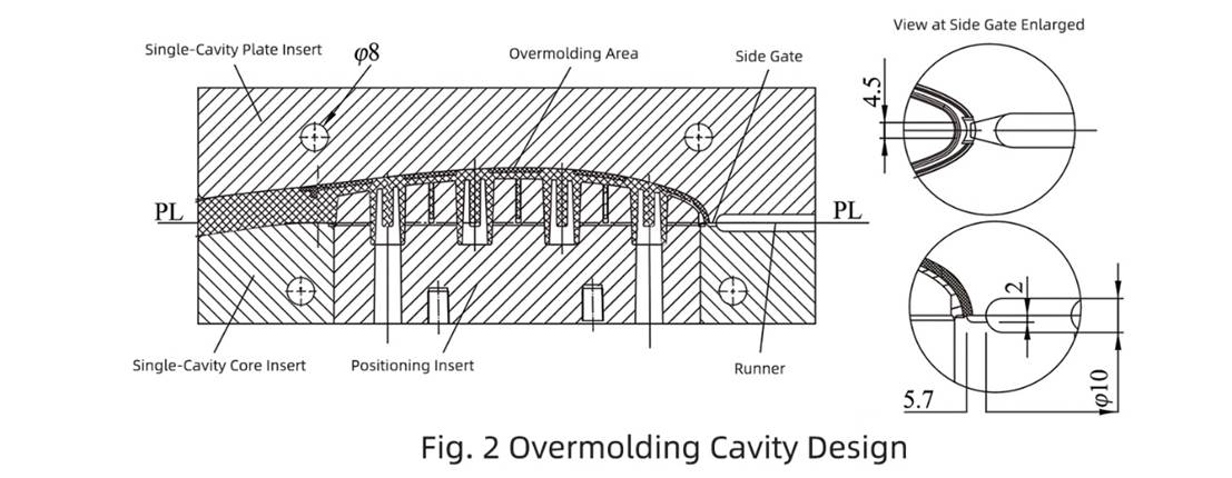
The part structure indicates that when using the mold transfer production method, the base part molded in the first mold is placed as a plastic insert into the second overmolding mold. After mold closure, injection proceeds. Therefore, the base part acts as a molding component of the overmolding cavity. However, this makes it difficult to position the gate for the overmolding cavity. The gate can only be located on the top surface of the overmolding area or at the 3mm wide opening on the left side of the overmolding area. If feeding from the top surface, a pinpoint gate must be used. This would require a three-plate mold structure. That structure is complex and has high manufacturing costs. Therefore, feeding from the 3mm wide opening on the left side is chosen. A side gate can be used for injection. This simplifies the mold to a two-plate structure. It is easier to manufacture and has lower cost. However, the gate remnant requires secondary trimming after molding. Thus, the overmolding mold adopts a two-plate structure with a side gate. Its cavity design is shown in Figure 2.
In the cavity design, positioning inserts are used to locate the base part. The parting surface (PL) of the base part serves as the parting surface for the overmolding cavity. This parting surface is used to create the single cavity plate insert and the single cavity core insert. Both the single cavity plate insert and the single cavity core insert are equipped with one φ8mm cooling channel each for cooling. The mold uses an overlap side gate. The gate dimensions are 5.7mm × 4.5mm × 2mm. A φ10mm round runner is used. The surface roughness of the runner and gate is Ra 0.8μm. To ensure the service life of the cavity walls, the single cavity plate insert and single cavity core insert are made from H13 alloy steel. The positioning inserts are made from 45# steel.
Mold Structure Design
The overall mold structure is shown in Figure 3. It uses a 1-cavity x 4 layout. The four cavities are labeled V1 to V4. The parting and structure design for each cavity is as shown in Figure 2. For the cooling system design, water channels W1 and W3 cool cavities V1 and V2. Water channels W2 and W4 cool cavities V3 and V4. Among these, W1 and W2 are the core cooling channels on the moving side. W3 and W4 are the cavity plate cooling channels on the fixed side. All channels have a diameter of φ8mm. The mold's gating system includes the main sprue (R1), primary runners (R2), secondary runners (R3), and gates (G1 to G4). The runners (R1 to R3) are identical for all four cavities, but the gate sizes differ. The gates for cavity V1 (G1) and cavity V4 (G4) have the same dimensions as shown in Figure 2. However, the gates for cavity V2 (G2) and cavity V3 (G3) have the same size but differ from the others. Therefore, gate balancing design is required. After gate balancing, gates G2 and G3 have a width of 2.8mm and a depth of 2mm.
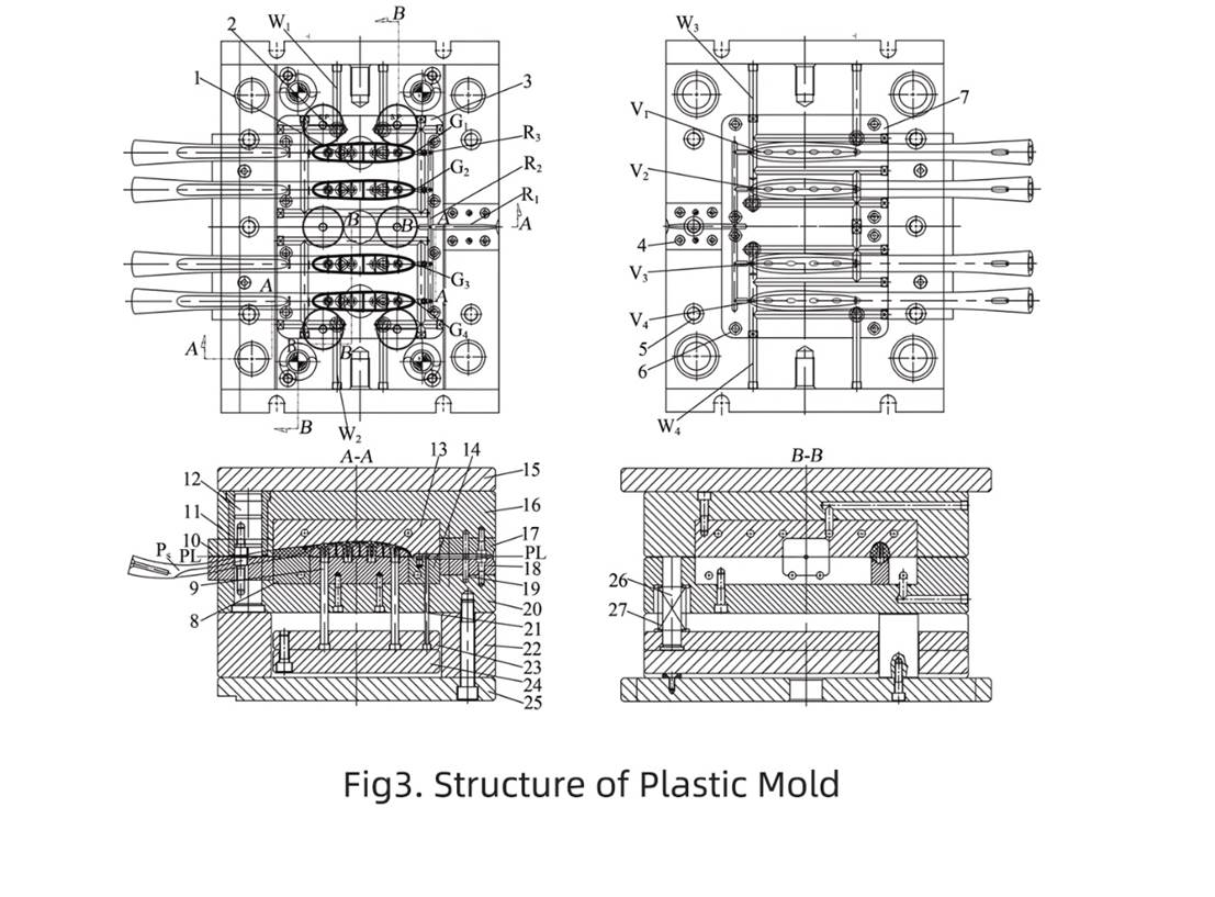
In the molding components design, the four single-cavity plate inserts (7) are combined to form the cavity plate insert assembly (13). The four single-cavity core inserts (3) are combined to form the core insert assembly (14). For the main sprue (R1), a common cylindrical sprue bushing is not used. Instead, an upper main sprue insert (17) and a lower main sprue insert (18) are employed. When the mold closes, these two inserts form the main sprue (R1). The part and runner system are ejected using ejector pins (9). The design of the gating system differs from a standard two-plate mold, mainly in the setup of the main sprue (R1). This is because the mold is intended for installation on a vertical injection molding machine. The vertical mold opening structure facilitates the operator's placement of the base part (PS). The mold's guiding mechanism uses four guide pillars (12) and four guide bushings (11) to ensure precise movement during mold opening.
Mold Installation and Working Principle
Mold Installation
The installation of most structural components is similar to that of a standard two-plate mold. The key difference lies in installing the lower main sprue insert (18) and the upper main sprue insert (17). Positioning pins are required for their accurate location. Both inserts also need designed alignment notches to ensure precise resetting when the mold closes. The ejector plate (24) simultaneously drives the ejector pins (9) and the runner ejector pins (21) to push out the molded parts and the runner system. Sealing rings (2) are installed into the corresponding grooves on the fixed mold plate (16) and the moving mold plate (20). They require a certain amount of compression to prevent water leakage from the cooling channels.
Mold Working Principle
The mold is mounted on an injection molding machine for the molding process, which proceeds as follows.
(1) Mold Closing. After the base parts are manually placed onto the positioning inserts (8), the mold closes at the parting surface (PL). The injection machine nozzle aligns with the entrance of the main sprue (R1) and injects the plastic melt. After completing filling, packing, and cooling phases, the mold waits for opening.
(2) Mold Opening. The moving platen of the injection machine moves upward, causing the mold to open at the PL surface. The molded parts detach from the cavity plate insert assembly (13) and remain on the core insert assembly (14).
(3) Ejection. A hydraulic cylinder rod inside the fixed mold pushes upward. This ejects the molded parts and the runner system from the core insert assembly (14). An operator manually removes the parts. Simultaneously, the gates are sheared off from the runner system at the gate locations.
(4) Reset. During reset, the ejector plate (24) first returns to its original position. The operator manually places new base parts onto the positioning inserts (8). Then, the mold closes at the PL surface, initiating the next injection cycle.


Sign in to leave a comment.