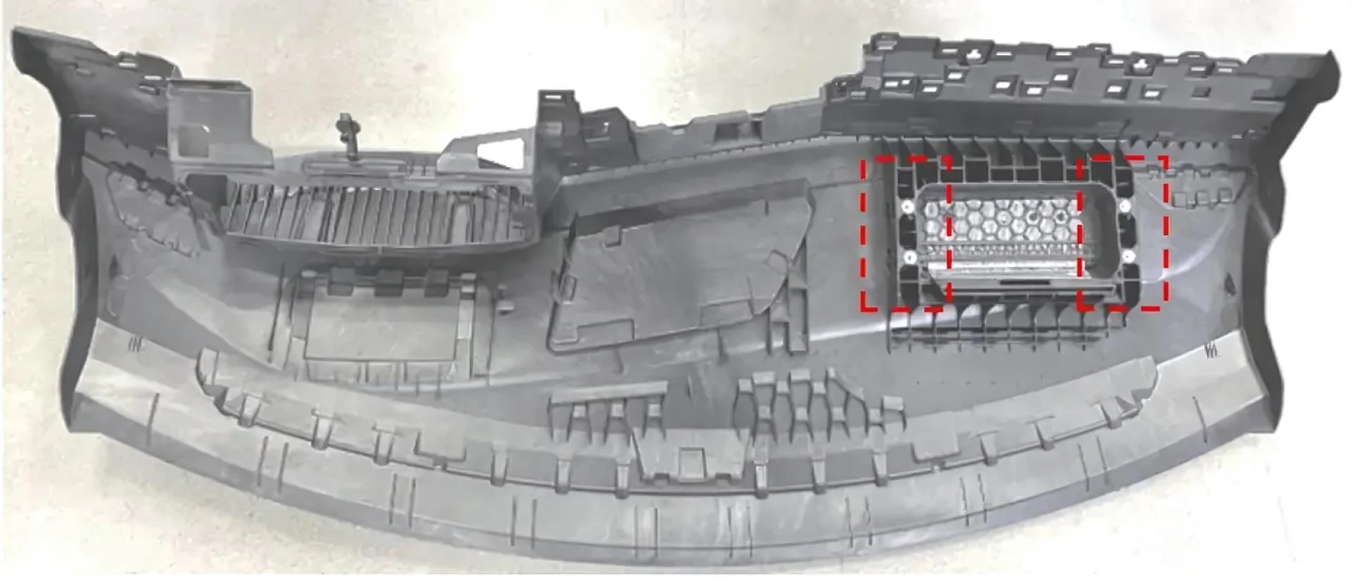
Figure 1 shows an automotive instrument panel skeleton. The material is PP+LGF20. The process requirement is physical foaming injection molding. The airbag frame area of the skeleton has four metal inserts. They are placed in corresponding areas by a robotic arm when the injection mold is open. During production, bulges often occur in the areas corresponding to these inserts, as shown in Figure 2. Local areas are softer due to insufficient cooling and are pushed up by the physical foaming action, forming bulges. To verify this point, the cooling time was extended from 30 s to 52 s in the process. The bulges no longer appeared in the corresponding areas. Based on this, the direction for improving the part's appearance defect was set as enhancing the cooling effect in those areas.

Figure 1

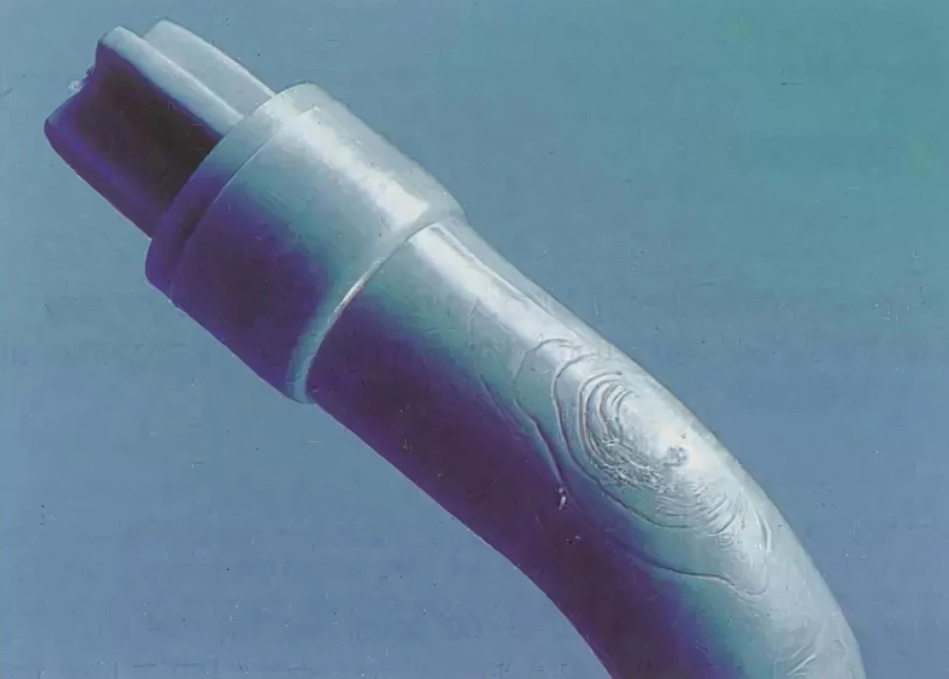
Figure 2
Due to high production volume, extending the cooling time solved the appearance defect but reduced daily output, creating significant delivery pressure. Autodesk Moldflow was used to build an analysis model identical to the actual situation. Mold flow analysis was conducted based on the actual mold's process parameters.
Analysis of the Cause of Molding Defects
Problem Location on the Part
The bulging area was examined using 3D software. Due to the insert shape, the part thickness in that area is inconsistent. The main wall thickness is 2.5 mm. The maximum thickness near the insert is about 8.485 mm, which is exactly where the bulge occurs, as shown in Figure 3. Further observation shows an adjacent area near the airbag mesh with a thickness of about 7.899 mm, but no bulge occurs there. Autodesk Moldflow was used to perform a cooling analysis on the part. The surface layer temperature, core temperature, and insert temperature at the bulging location were analyzed.
Cooling Analysis Results
Table 1 shows data summarized from the Autodesk Moldflow cooling simulation. With a cooling time set to 30 s, the part's core temperature in the insert area is 158 °C, while in the mesh area it's 164 °C. The latter has a slightly higher core temperature but no bulge. This indicates the core temperature is not the cause of the bulge. The difference might be in the part's surface temperature.
| Parameter | Insert Area (Cooling Time/s) | Mesh Area (Cooling Time/s) | ||
| Wall Thickness/mm | 8.5 | 7.9 | ||
| Cooling Time/s | 30 | 52 | 30 | 52 |
| Core Temperature/°C (required < 125°C) | 158 | 120 | 164 | 118 |
| Surface Temperature/°C (required < 80°C) | 91.5 | 68.5 | 62 | 52 |
| Insert Temperature/°C | 121 | 100 | / | / |
| Bulge | Yes | No | No | No |
The part's surface temperature in the insert area is 91.5 °C, while in the mesh area it's 62 °C. It can be inferred that the higher surface temperature in the insert area makes the surface plastic softer. Under physical foaming, the surface is pushed up by the compressed gas, forming a bulge. In the mesh area, the surface temperature is only 62 °C; the surface plastic has already hardened and cannot be pushed up. The metal insert has significant heat absorption compared to plastic. The insert transfers absorbed heat to the adjacent plastic area, causing noticeably high surface temperature in that part region.
Based on this reasoning, the insert temperature was further analyzed. Table 1 lists insert temperatures under different cooling times. With a 30 s cooling time, the insert temperature is 121 °C, and bulges appear. With a 52 s cooling time, the insert temperature is 100 °C, and no bulges appear.

Figure 3
Analysis Based on Mold 3D Structure
The insert in contact with the bulging area is a nut. Its location corresponds to a large angled-lifter mechanism in the mold. During mold opening, the insert is placed on a mold insert of the angled-lifter by the robotic arm. Then mechanisms reset, the mold closes, and the cycle begins. There is a clearance of about 0.1 mm per side between the mold insert and the insert's inner hole. The insert bottom contacts the angled-lifter, as shown in Figure 4. Due to limited steel space around the mold insert and angled-lifter mechanism, conventional cooling channels cannot be designed. Combined with the above analysis, the insert acts as a heat accumulator, which is the root cause of the bulge.
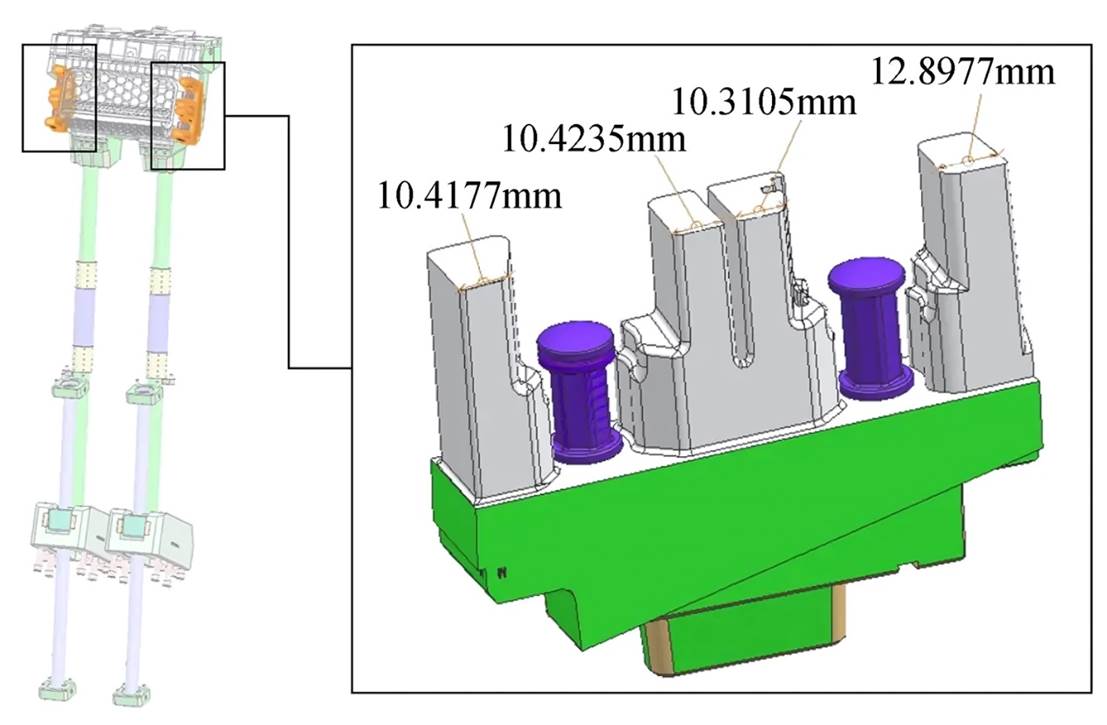
Figure 4
Improvement Plan Based on Mold Flow Analysis
Cooling Analysis Based on the Optimization Plan
By reviewing the mold's 3D structure, a plan was proposed to optimize cooling both outside and inside the insert area. Outside the insert, conformal cooling channels are intended to optimize cooling. Inside, cooling the insert aims to fundamentally eliminate the hot spot.
The angled-lifter area has limited steel space for conventional channels. It was improved using 3D printing technology to create conformal cooling channels, connecting them to the peripheral channels. To enhance the insert's cooling effect, a non-toxic, environmentally friendly high-thermal-conductivity material similar to beryllium copper was selected. This allows the insert's exterior to be surrounded by cooling channels for optimal effect.
Figure 5 shows the cooling effects using conventional channels and conformal channels at a 52 s cooling time. Table 2 summarizes the improvements in part core temperature, surface temperature, and insert temperature for both channel types. It shows that at 52 s cooling time, using high-thermal-conductivity material and conformal channels significantly improves part temperature. However, the insert temperature still doesn't improve. Under the insert's "heating" effect, bulges might still occur after ejection. This means cooling time cannot be reduced to 30 s.
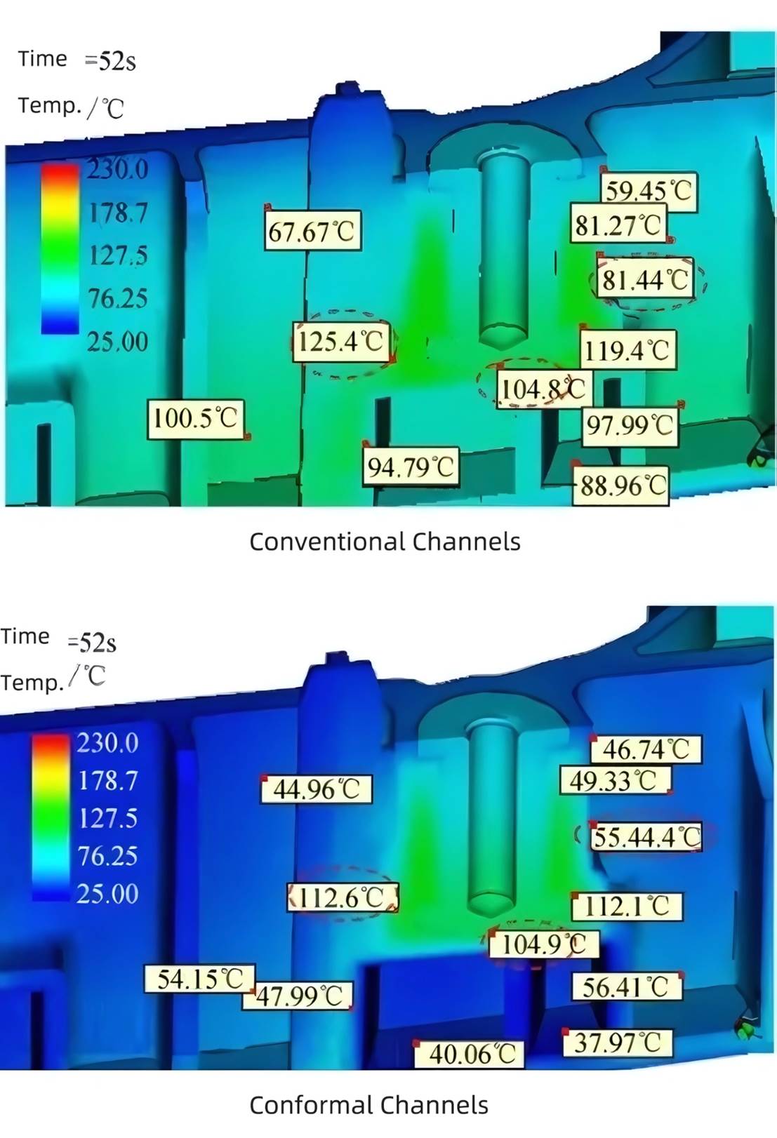
Figure 5
| Analysis Condition | Analysis Part | Conventional Cooling Channels | Conformal Cooling Channels | Improvement Rate |
| 1. Fixed side mold temp: 40°C 2. Moving side mold temp: 25°C 3. Melt temperature: 230°C 4. Cooling time set: 52 s | Part Core | 125.4°C | 112.6°C | 10% |
| Part Surface | 70°C | 30°C | 31% | |
| Insert | 105°C | 105°C | 0 |
Figure 6 compares analysis results before and after cooling the insert, with a cooling time set to 20 s. Without insert cooling, its temperature is as high as 120.8 °C, and the adjacent part core temperature reaches 147.7 °C. With insert cooling, its temperature drops to 68.09 °C, and the adjacent part core temperature drops to 129.6 °C. This shows significant cooling improvement after adding insert cooling, as shown in Table 3.

Figure 6
| Analysis Condition | Analysis Part | Conventional Cooling Channels | Conformal Cooling Channels | Improvement Rate |
| 1. Fixed side mold temp: 40°C 2. Moving side mold temp: 25°C 3. Melt temperature: 230°C 4. Cooling time set: 20 s | Part Core Temperature | 148°C | 130°C | 12% |
| Insert Temperature | 121°C | 68°C | 44% |
Optimizing Mold Structure Based on Cooling Analysis Results
Based on the above analysis and the mold's 3D structure, structural optimization was further evaluated. For cooling the insert exterior, a cooling insert was added in the original angled-lifter area. This insert contains 3D-printed conformal cooling channels inside, as shown in Figure 7. For cooling the insert interior, the original positioning insert was modified by drilling holes, turning it into a "gas-assisted device", as shown in Figure 8. Simultaneously, air channels were set in the angled-lifter mechanism to implement the gas-cooling plan, as shown in Figure 9.

Figure 7

Figure 8

Figure 9
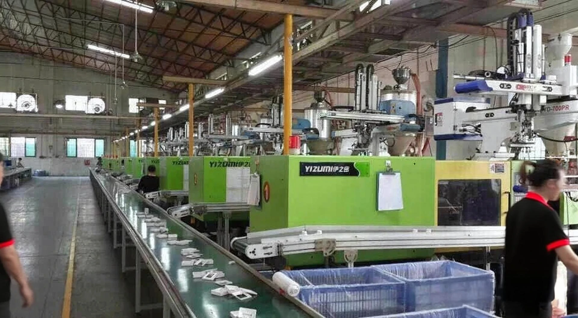
The optimized mold was tested, as shown in Figure 10. With cooling time set to 19.6 s, no bulges appeared on the part. Based on these test results, the mold's cooling time limit can reach 20 s, fully meeting the target optimization cycle time of 30 s. The measured insert temperature was 65.9 °C, compared to the analysis result of 68 °C in Table 3. The mold flow analysis results are accurate and have high precision.

Figure 10


Sign in to leave a comment.