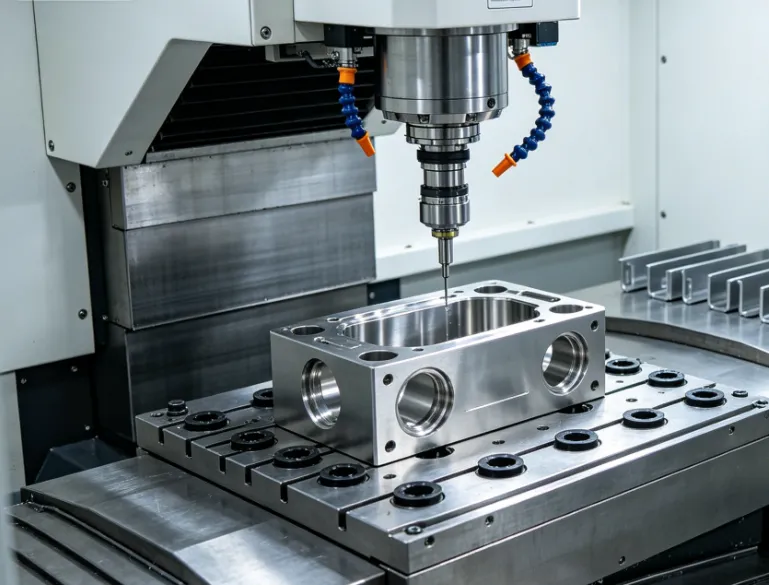

In high-tolerance industries like medical device manufacturing, semiconductor processing, and aerospace engineering, a deviation of a single micron can mean the difference between a flawless production run and catastrophic assembly failure. Industrial manufacturing data from 2026 highlights that over 70% of component mechanical failures are traced back to improper geometric dimensioning or residual stresses induced during sub-optimal milling cycles. This comprehensive technical guide outlines the critical operational benchmarks required to evaluate mechanical tolerances, surface typography, and structural integrity when sourcing high-precision components.
1. Controlling Tolerance Stack-Up via Advanced GD&T
When engineering complex multi-component assemblies, relying solely on linear tolerances is a primary cause of misalignment during final integration.
Advanced mechanical designs utilize Geometric Dimensioning and Tolerancing (GD&T) to define the exact relationship between part features based on functional datums. True position, concentricity, and profile perpendicularity must be calculated with extreme precision to prevent tolerance stack-up—the cumulative effect of individual part variances. To achieve a repeatable true position tolerance under $0.01\text{ mm}$, machine shops must utilize ultra-rigid fixturing and high-accuracy machining centers. For engineers seeking to optimize their part design for high-yield manufacturing, partnering with an established production facility like Baosheng Industry ensures that complex GD&T callouts are properly interpreted and executed on the factory floor.
2. Managing Surface Roughness ($R_a$) and Dynamic Fatigue Life
Surface finish is not merely an aesthetic requirement; it is a critical determinant of a component's friction coefficient, wear resistance, and long-term fatigue life.
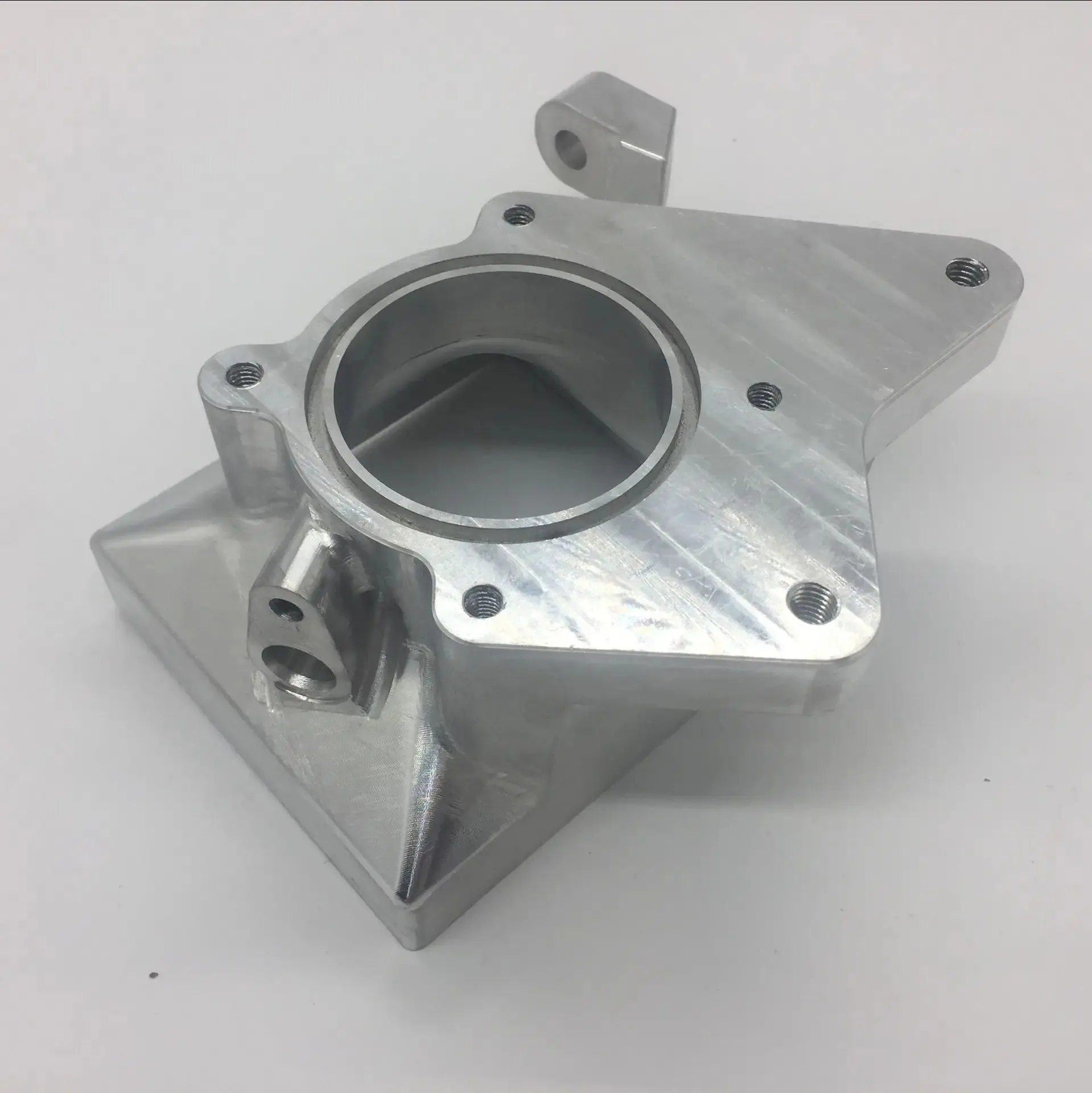
High-stress applications require a low micro-roughness value ($R_a$) to eliminate micro-grooves that act as stress concentration points where fatigue cracks can initiate. Achieving a mirror-like finish of $R_a\ 0.4\ \mu\text{m}$ or lower directly off the machine tool demands a highly calibrated synchronization of spindle speed, feed rate, and cutting tool geometry. When sourcing custom precision CNC machining parts, understanding the correlation between chip load and surface topography allows procurement teams to balance performance requirements with machining time, preventing over-specification while ensuring part durability under cyclic loads.
3. Mitigating Thermal Stress and Substrate Work Hardening
The mechanical energy expended during high-speed cutting transformations into intense localized heat at the shear zone, posing a significant risk to the part's crystalline structure.
Materials with poor thermal conductivity, such as stainless steel grades and nickel superalloys, tend to work-harden rapidly if the cutting edge dwells or slides instead of shearing cleanly. This thermal concentration can introduce residual tensile stresses into the sub-surface layers of the component, leading to dimensional warping over time. Advanced machining protocols eliminate this risk by deploying flood or high-pressure through-spindle cooling systems to rapidly evacuate heat through the sheared chips, effectively preserving the native mechanical properties and grain structure of the metal substrate.
4. Micro-Machining and Micro-Wall Aspect Ratio Limits
As electronic and medical components shrink, the demand for micro-machining parts with ultra-thin walls, micro-slots, and deep high-precision bores continues to grow.
Machining these micro-features presents a unique challenge: tool deflection. As the aspect ratio (the ratio of feature depth to tool diameter) increases beyond 5:1, standard carbide tools begin to bend under cutting forces, resulting in tapered walls and dimensional drift. In 2026, premium machine cells combat this by utilizing specialized diamond-coated micro-cutters and adaptive high-frequency spindles capable of maintaining continuous concentric cutting paths. Designers must account for these material constraints, providing adequate draft angles or wall thickness variations to prevent component deflection during final finishing passes.
5. Automated Coordinate Metrology and Closed-Loop Verification
A high-precision part is only as reliable as the quality inspection framework used to validate its geometry.
Modern zero-defect quality control protocols have evolved past manual micrometers to fully automated Coordinate Measuring Machines (CMM) and non-contact optical comparators. These metrology systems cross-reference the physical part against the original 3D CAD model by scanning thousands of microscopic data points. Implementing closed-loop verification—where inspection data is fed directly back into the CNC control module to auto-adjust tool offsets—is the definitive method used by top-tier fabricators to eliminate human error and maintain tight control limits across long, continuous production campaigns.
Conclusion
Procuring premium-grade machined parts requires a systematic understanding of the mechanical, thermal, and geometric dynamics that govern precision manufacturing. By focusing on stringent GD&T compliance, optimized surface roughness limits, and closed-loop metrology verification, you secure a reliable supply chain capable of delivering components that perform flawlessly under the most rigorous operating conditions. Aligning your product designs with these rigorous manufacturing boundaries is the ultimate strategy to ensure structural safety, longevity, and cost efficiency in today's demanding global marketplace.























Sign in to leave a comment.