
A magnetic water flow meter is one of the most reliable and widely used instruments for measuring the flow rate of conductive liquids. Known for its accuracy, durability, and lack of moving parts, it is particularly effective in applications where traditional mechanical or turbine meters fail due to sediment, corrosion, or high viscosity. Understanding its working principle requires exploring electromagnetic theory, sensor engineering, and the unique characteristics of conductive fluids. This article provides a comprehensive explanation of how a magnetic water flow meter operates, why it is used across industries, and what technical features make it exceptionally dependable.
Understanding the Fundamentals of Magnetic Flow Measurement
The Basis of Electromagnetic Induction
At the core of the magnetic water flow meter’s operation lies Faraday’s Law of Electromagnetic Induction. Faraday’s Law states that when a conductive fluid flows through a magnetic field, it generates an electrical voltage proportional to the velocity of that fluid. The magnetic field is produced by coils surrounding the flow tube, while electrodes measure the voltage that appears when a conductive medium passes through this field.
This scientific foundation eliminates the need for mechanical interaction with the fluid. The fluid itself becomes the conductor, the magnetic field acts as the energizing agent, and the electrodes detect the flow signal. This makes magnetic meters ideal for measuring water, wastewater, slurries, and chemicals because none of these substances contact moving parts.
Conductivity Requirements of the Fluid
For a magnetic water flow meter to operate effectively, the fluid must be electrically conductive. Pure distilled water, for instance, does not meet the conductivity threshold, while tap water, river water, and industrial liquids typically do. Conductivity allows electrons within the fluid to move under the influence of the magnetic field, generating the measurable voltage.
This requirement explains why magnetic flow meters excel in municipal water systems, chemical dosing, and wastewater treatment plants. The natural ions in the liquid ensure a consistent measurable signal.
Components That Enable Magnetic Flow Measurement
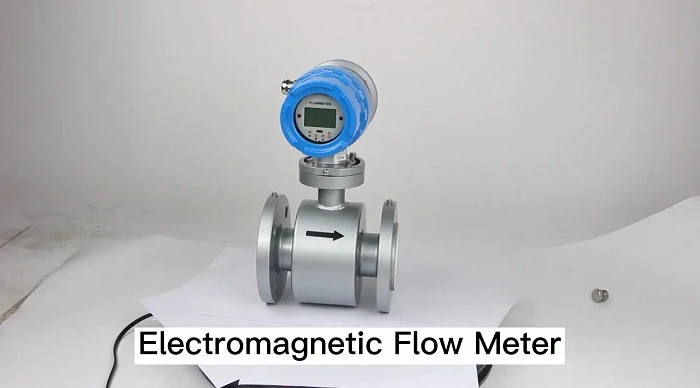
The Flow Tube and Magnetic Coils
At the center of the device is the flow tube—typically lined with a non-conductive material such as rubber, PTFE, or ceramic. This liner prevents electrical shorting and ensures that the measured voltage appears only between the electrodes. Around the tube are electromagnetic coils that generate a stable and controlled magnetic field when energized.
The purpose of the magnetic field is to create a uniform interaction between the fluid and the electrical measurement system. When the coils are activated, the field permeates the entire cross-sectional area of the flow tube, ensuring that any conductive fluid passing through will generate a measurable voltage.
Electrodes and Signal Processing
Electrodes are placed opposite each other inside the flow tube. Their purpose is to detect the induced voltage created by fluid motion. The faster the fluid moves, the greater the voltage generated between the electrodes. This voltage is extremely small—typically in the millivolt range—so it must be carefully amplified and processed.
Modern signal transmitters attached to the magnetic water flow meter filter out electrical noise, compensate for turbulence, and convert the induced voltage into readable flow data. The transmitter then outputs measurements in terms of volume flow rate, often in liters per second or gallons per minute.
How Flow Rate Is Calculated in Magnetic Water Flow Meters
Relationship Between Velocity and Induced Voltage
The key mathematical principle behind a magnetic water flow meter is that voltage is directly proportional to the velocity of the fluid. Faraday’s Law defines this relationship in the equation:
E = k × B × D × V
Where:
E is the induced voltage
k is a calibration constant
B is the magnetic field strength
D is the diameter of the flow tube
V is the fluid velocity
Because the pipe diameter is constant and the magnetic field is stable, the only variable affecting voltage is the velocity of the water. The transmitter uses this measurable voltage to calculate flow rate.
Converting Velocity to Volume Flow
Once the velocity is known, volume flow is determined by multiplying velocity by the cross-sectional area of the pipe. This provides a continuous measurement of the total amount of water passing through the meter.
This calculation method allows magnetic flow meters to measure flow with high precision even at low velocities or in fluids with suspended solids—conditions that mechanical meters struggle with.
Operational Advantages of Magnetic Water Flow Meters
No Moving Parts and Minimal Wear
One of the most significant advantages of a magnetic water flow meter is the complete absence of moving components. Traditional mechanical meters rely on turbines or paddles that must physically interact with the liquid. In contrast, magnetic meters do not contact the fluid beyond the electrodes, which themselves remain protected within the lining material.
This design ensures exceptionally long service life, reduces maintenance, and eliminates common problems such as clogging, corrosion, or mechanical degradation.
High Accuracy in Difficult Conditions
Magnetic meters excel in conditions where other meters fail. They maintain accuracy even when the liquid contains sand, sludge, chemicals, or biological matter. The uniform magnetic field and internal lining help ensure stable readings regardless of internal buildup or sediment.
Additionally, the meter handles fluctuating flow rates better than mechanical systems, maintaining precision even during rapid changes in velocity.
Applications Where Magnetic Water Flow Meters Excel
Municipal and Industrial Water Systems
In water distribution networks, magnetic flow meters provide reliable data for billing, consumption tracking, and leak detection. Their durability makes them suitable for large municipal pipelines and smaller sector applications.
In industrial environments, these meters measure chemicals, slurries, oils with conductive additives, or any water-based liquid requiring precise monitoring.
Wastewater Treatment and Sludge Handling
Wastewater is naturally conductive and often contains suspended solids. A magnetic water flow meter is perfect for these environments because solids do not hinder its operation. Sludge mixtures, aerated water, and chemical injection lines benefit from the meter’s stability and non-intrusive measurement method.
Factors Affecting the Performance of Magnetic Flow Meters
Electrical Noise and Grounding
Because magnetic flow meters detect millivolt signals, proper grounding is essential. Nearby equipment can cause electrical interference that must be filtered during signal processing. Modern transmitters use advanced algorithms to stabilize readings, but proper installation is still critical.
Fluid Conductivity and Temperature
Conductivity must remain within the manufacturer’s recommended range. Extremely low conductivity results in weak or unstable voltage signals. Temperature can also affect conductivity, but the sensors compensate automatically when configured correctly.
Conclusion
A magnetic water flow meter operates on the principle of electromagnetic induction, using the movement of a conductive liquid through a magnetic field to generate a measurable voltage. This voltage, proportional to fluid velocity, allows precise determination of flow rate without any mechanical interaction. With no moving parts, high accuracy, and exceptional durability, magnetic flow meters are indispensable tools in water management, industrial processes, and wastewater treatment. Their reliability stems from the elegant simplicity of Faraday’s Law and the advanced engineering that transforms electromagnetic principles into practical and dependable measurement instruments.


Sign in to leave a comment.