Injection molding projects often begin with the plastic part itself. A buyer sends a CAD file. A designer checks wall thickness. A moldmaker reviews shrinkage, gates, draft, undercuts, and expected production volume. At first glance, the discussion may seem focused only on the finished plastic part.
In reality, the mold structure behind that part decides whether the project will run smoothly or become difficult during trial and production.
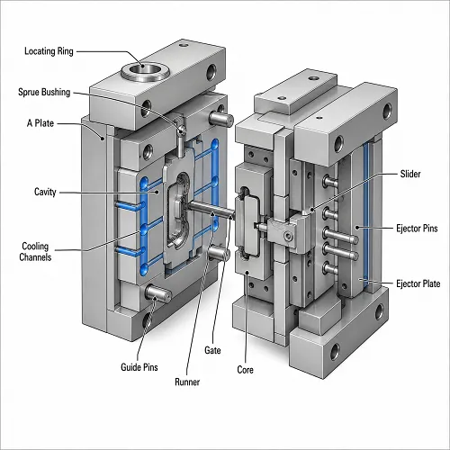
An injection mold is not just a cavity cut into steel. A working mold contains many systems that must fit together: the mold base, core, cavity, runner, gate, ejector system, cooling channels, vents, slides, lifters, inserts, and alignment parts. Anyone reviewing a new plastic part should have at least a basic understanding of Injection Mold Components, because these components affect tooling cost, lead time, cycle time, part quality, and long-term production stability.
A molded part may look simple from the outside, but the mold behind it may be much more complex than expected.

Mold Structure Starts With the Part Geometry
The shape of the plastic part determines the basic mold structure. A flat cover with clean draft and no undercuts can often use a simple open-and-shut mold. A housing with side holes, snap hooks, deep ribs, or internal clips may need slides, lifters, or other moving mold components.
This is where many cost differences begin. Two parts with similar size may not require similar molds. One part may only need a core, cavity, runner, gate, cooling lines, and ejector pins. Another part may require side actions, replaceable inserts, special venting, angled lifters, or a hot runner system.
A small side hole can change the whole mold layout. If the hole cannot be formed in the mold opening direction, the tool may need a slide. That slide needs space, movement, locking, wear plates, and maintenance access. The plastic feature may look minor, but the mold structure becomes more expensive and more sensitive to wear.
This is why DFM review should happen before mold manufacturing starts. The goal is not only to check whether the part can be molded. The goal is to understand what kind of mold the part will require.
Core and Cavity Decide More Than Shape
The core and cavity are the mold surfaces that create the molded part. The cavity usually forms the outside or appearance surface, while the core forms the inside geometry, ribs, bosses, holes, pockets, and hollow areas.
These components affect more than the visible shape. They influence draft, parting line position, surface finish, shrinkage allowance, dimensional accuracy, and ejection behavior.
For cosmetic parts, the cavity surface may need careful polishing, texture, or EDM finish control. For parts with tight tolerances, the core and cavity must account for material shrinkage and possible steel-safe correction after trial. If the moldmaker removes too much steel too early, correcting the dimension later can become difficult or impossible without welding or insert replacement.
Core and cavity design also affects how the part releases from the mold. A tall rib, deep boss, or textured wall may grip the core strongly after cooling. Without enough draft or proper ejection support, the molded part may show drag marks, stress whitening, ejector marks, or deformation.
Good core and cavity design is not only about machining accuracy. It is about understanding how plastic cools, shrinks, sticks, and releases from steel.
Runner and Gate Design Control How Plastic Enters the Part
The feeding system carries molten plastic from the machine nozzle into the cavity. In a cold runner mold, this system includes the sprue, runner, gate, and sometimes cold slug wells. In a hot runner mold, heated manifold components keep the plastic molten closer to the gate.
Gate design is one of the most important choices in mold structure. The gate controls where plastic enters the cavity, how the flow front moves, where weld lines may form, how the part packs, and where the gate mark appears.
A gate that is too small may freeze early and limit holding pressure. This can cause sink marks, poor packing, or dimensional variation. A gate that is too large may leave a visible vestige or create trimming issues. A poorly placed gate may push weld lines into cosmetic or functional areas.
In multi-cavity molds, runner balance becomes even more important. If one cavity fills faster than another, part weight and dimensions may vary across the mold. The machine settings may look stable, but the mold layout itself may be creating imbalance.
A good runner and gate design should match part geometry, wall thickness, resin flow, surface requirements, production volume, and cost target.
Cooling Channels Affect Cycle Time and Dimensional Stability
Cooling is often the longest part of the injection molding cycle. A mold may fill in seconds, but the part must cool enough to eject without warping, sinking, sticking, or changing shape after release.
Cooling channels remove heat from the mold steel. Their location, diameter, flow path, and balance affect cycle time and part stability. If cooling channels are too far from the cavity, heat removal may be slow. If cooling is uneven, one side of the part may shrink differently from the other side.
This can lead to warpage, dimensional drift, sink marks, or long cooling cycles. The issue may not appear immediately at mold opening. A part can look acceptable when ejected and then change shape after sitting outside the mold.
Deep cores, thick bosses, large flat surfaces, and complex geometry often need extra cooling attention. Baffles, bubblers, copper alloy inserts, or conformal cooling may be used when straight drilled channels cannot reach critical hot spots.
Cooling design should not be treated as a secondary detail. It can decide whether the mold runs efficiently in real production.
Ejection Design Protects the Part After Cooling
Once the part cools, the mold opens and the ejector system pushes the part off the core. Common ejector components include ejector pins, ejector sleeves, ejector blades, ejector plates, return pins, and stripper plates.
Ejection looks simple, but poor ejector design can damage a part that was otherwise molded correctly. If ejector pins are too small, poorly placed, or unevenly balanced, the part may show pin marks, dents, whitening, bending, or cracks.
The risk is higher when parts have deep ribs, tall bosses, thin walls, textured surfaces, or poor draft. A warm plastic part still has limited stiffness at ejection. Too much force in the wrong area can deform the part before it fully stabilizes.
Good ejection design considers the shape of the part, expected shrinkage, draft angle, surface finish, and core grip. In some cases, a stripper plate or larger ejection area is better than relying only on small ejector pins.
The finished part may fail not because the cavity was wrong, but because the part was not released correctly.
Venting Prevents Burn Marks and Short Shots
Air inside the cavity must escape as molten plastic fills the mold. If trapped air has nowhere to go, the flow front can hesitate, compress the air, or burn the material. The result may be burn marks, short shots, weak weld lines, or poor surface finish.
Vents can be placed along parting lines, around inserts, near ejector pins, or at the end of flow. Vent depth must be controlled carefully. If the vent is too shallow, air cannot escape. If the vent is too deep, flash can occur.
Venting also changes over time. During production, residue can build up and block vent paths. A mold that ran well during early trial can develop burn marks later if vents are not maintained.
Venting is a small detail on the mold drawing, but it has a large effect on molding stability.
Slides, Lifters, and Inserts Increase Mold Capability
Some plastic part features cannot be formed by a simple open-and-shut mold. Side holes, undercuts, snap features, grooves, and internal hooks may require slides or lifters.
Slides move sideways to form lateral features. Lifters move at an angle to release internal undercuts. Inserts may be used for difficult details, high-wear areas, repairable zones, or steel-safe dimensional adjustments.
These components make more complex plastic parts possible, but they also increase mold cost and maintenance needs. Moving components require fitting, locking, lubrication, wear control, and enough space inside the mold base.
This does not mean slides or lifters should always be avoided. Sometimes they are necessary. But during design review, it is worth asking whether a small feature can be modified to simplify the mold. Removing one undercut can sometimes reduce cost, shorten lead time, and improve mold reliability.
Mold Components Affect Cost, Trial, and Production
Injection mold cost is not only based on part size. Cost depends on the mold structure required to produce the part consistently.
A simple mold with a basic gate and straight ejection may be relatively economical. A mold with hot runners, multiple slides, lifters, polished cavity surfaces, tight shutoffs, conformal cooling, and replaceable inserts will cost more because it requires more engineering, machining, fitting, and trial work.
Mold components also affect what happens after the mold is built. A poor gate can create filling problems. Weak cooling can create warpage. Bad ejection can leave marks or bend the part. Poor venting can cause burns. Weak alignment can lead to flash or mismatch.
A lower-cost mold is not always the lowest-cost production choice. If the mold needs repeated corrections, runs slowly, or creates unstable parts, the project can become more expensive over time.
Final Thoughts
Understanding mold structure helps buyers and engineers have better discussions before tooling begins. The goal is not to memorize every mold component. The goal is to understand that each component has a job, and each job affects the final plastic part.
The core and cavity shape the part. The runner and gate control material flow. Cooling channels manage heat. Ejector parts release the molded part. Vents remove trapped air. Slides, lifters, inserts, and alignment parts support more complex mold designs.
A good injection mold is not just a tool that makes a plastic shape. It is a controlled system built around part geometry, material behavior, production volume, surface requirements, and long-term reliability. When those details are reviewed early, the mold trial becomes easier, and the final molded parts are more stable in production.


Sign in to leave a comment.