The Language of Precision in Construction
Imagine this scenario: An architect hands over a stunning, photorealistic 3D model to a contractor. It looks complete. Yet, the contractor opens the file and declares it "unbuildable." Why? While the geometry looked perfect, the underlying data, specifications, connections, and precise dimensions were missing.
This disconnect is the primary reason the Architecture, Engineering, and Construction (AEC) industry adopted Building Information Modeling (BIM) Level of Detail (or Development), commonly known as LOD. (BIM is a digital representation of the physical and functional characteristics of a facility. LOD specifies the level of detail and reliability of model elements at various project stages.)
In Building Information Modeling (BIM), a 3D model is not a static digital sculpture; it is an evolving database that matures over time. LOD is the industry-standard language (defined primarily by the BIMForum and AIA) that specifies the maturity, reliability, and precision of a model element at any given stage of a project. It answers the critical question: "How much can I trust this model right now?"
This guide breaks down the stages of LOD, clarifying what is required at each step of the BIM modeling process to ensure smooth collaboration from concept to operations.
The Crucial Distinction: Detail vs. Development
Before diving into the stages, a critical clarification is needed. While often used interchangeably with "Level of Detail," the industry standard (AIA G202) actually refers to "Level of Development."
- Level of Detail refers to how an object looks and its graphical complexity.
- Level of Development refers to the reliability of the geometry and the attached data for specific uses, such as construction, installation, or cost estimation.
In BIM practice, Level of Development is the focus. A chair may have great graphical detail but lack reliable data.
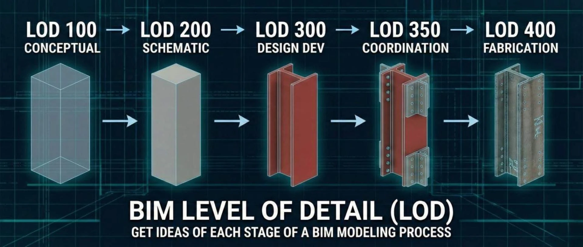
The Six Stages of LOD: From Concept to Reality
To illustrate these stages, we will use a common building element: a structural steel column.
LOD 100: Conceptual (The Placeholder)
At this stage, the element is represented graphically with a generic symbol or block. It indicates that something exists, but its shape, size, and exact location are fluid.
- The Steel Column Example: A simple vertical line or a generic bounding box in the model indicating "there will be a structural support here somewhere."
- Reliability: None for construction. Used only for very early conceptual spatial planning and rough area calculations.
LOD 200: Schematic Design (The Generic System)
The element is modeled as a generic system with approximate quantities, size, shape, location, and orientation.
- The Steel Column Example: A generic square or round column shape. We know it’s approximately a 12" x12" column located on Gridline A-5, but we don't yet know the specific steel profile (e.g., W12x53).
- Reliability: Good for preliminary structural analysis and early architectural coordination, but not for ordering materials.
LOD 300: Design Development (The Specific Element)
This is a major leap in precision. The object is defined as a specific system in terms of quantity, size, shape, location, and orientation. Specific engineering data is attached.
- The Steel Column Example: The model now shows a specific W12x53 steel I-beam profile. Its exact height and location are determined by structural calculations.
- Reliability: Accurate for generating traditional 2D construction documents (plans and sections) and general coordination.
LOD 350: Construction Documentation (The Coordination Stage)
This is a key stage for modern BIM coordination. It includes all details from LOD 300, plus interfaces with other building systems. It shows how different parts connect.
- The Steel Column Example: The W12x53 column now includes base plates, cap plates, and connection details for incoming beams. It shows exactly how it interacts with the concrete footing below it.
- Reliability: Essential for Clash Detection (the process of identifying spatial conflicts between building systems). This level allows the GC (General Contractor) to see if a duct will hit the column’s connection plate, rather than just the column shaft.
LOD 400: Fabrication & Assembly (The Shop Drawing)
The model element is detailed enough for fabrication and assembly. This is typically modeled by subcontractors or fabricators, not the design team.
- This is a virtual shop drawing. It includes exact weld types, bolt holes, copes, and assembly instructions. The steel fabricator can feed this model directly into CNC machinery to cut the beam.
- Reliability: 100% ready for manufacturing and on-site installation (meaning construction elements can be produced directly from this model).
LOD 500: As-Built / Record Model (The Digital Twin Base)
LOD 500 is not about greater graphical detail; it is about verified reality. It is a field-verified representation of what was actually installed, which may differ slightly from the LOD 400 design.
- The Steel Column Example: The geometry reflects the exact installed position. Crucially, it includes non-graphical data like serial numbers, installation dates, maintenance schedules (records of required service), and warranty information.
- Reliability: Used by Facility Managers for operations and maintenance throughout the building's life.
The "Goldilocks" Principle: Avoiding Over-Modeling
Understanding LOD is vital for project efficiency because it prevents "over-modeling."
A common mistake is demanding LOD 400 for everything too early. Modeling every bolt on a steel structure during the Schematic Design phase (LOD 200) is a massive waste of time and budget, and it bloats the file size, making the model unusable.
Successful BIM execution relies on defining the minimum LOD necessary for a specific project milestone. You need just enough detail to make the next decision, and no more.
Conclusion
BIM Level of Detail is more than just a technical specification; it is a communication contract between project stakeholders. By clearly defining expectations at each stage of the BIM modeling process, teams can align expectations, reduce rework, and ensure the digital model seamlessly translates into the physical world.
Looking to implement standardized LOD in your next project? Navigating the complexities of LOD requirements requires expertise. Professional BIM Modeling Services can help ensure your models are delivered at the exact level of development required for design, coordination, and fabrication success.
This article was originally published on the BIM Services India blog. To read the full guide and explore more examples of LOD in action, visit: BIM Level of Detail (LOD) – Get ideas of each stage of a BIM modeling process.


Sign in to leave a comment.