What This Project Is and Why It Exists
Toll collection is one of those things that feels like it should have been automated a long time ago. Waiting in a lane while someone manually takes cash, makes change, and waves you through is slow and unnecessary given what even basic microcontrollers can do now. This Arduino project is a scaled-down but fully functional take on that idea. It uses an RFID card to simulate a prepaid toll pass, a couple of IR sensors to detect when a vehicle is present, and a servo motor to physically open and close a gate. The result is a system that runs through the entire toll cycle without anyone touching anything.
The project is primarily aimed at students and people just starting out in electronics, and it genuinely lives up to that promise. The component list is affordable, the wiring is manageable on a breadboard without any soldering, and the code structure is laid out in a way that makes sense to follow even if you're still learning. That said, there is real logic happening here. This is not just blinking an LED. It coordinates multiple sensors, a payment validation step, and a mechanical actuator in sequence, which gives it a satisfying feel when it all works.
The Hardware Involved
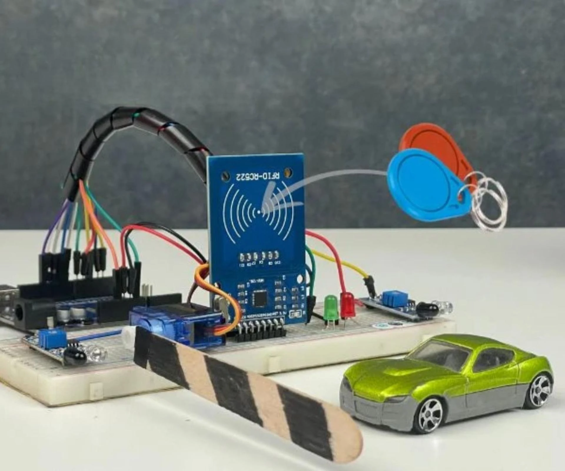
The build centers on an Arduino Uno, which reads sensors, handles the RFID communication, and drives the servo. Around it, you wire up an RC522 RFID reader module, two IR sensor modules, one SG90 servo motor, a red LED, a green LED, and a breadboard to hold it all together. Three RFID tags or cards represent different vehicles with different pre-loaded balances. The total cost lands under thirty dollars, which is part of why it works so well as a teaching project.
The RC522 talks to the Arduino over SPI, which takes up a chunk of the digital pins: SS on pin 10, RST on pin 9, SCK on pin 13, MOSI on pin 11, MISO on pin 12. One thing that trips people up here is power. The RFID module needs 3.3V, not 5V. Everything else runs at 5V. Confusing those two voltages when wiring is one of the most common reasons the RFID reader refuses to respond at all. The IR sensors go to pins 2 and 3, the servo signal wire to pin 5, the red LED to pin 6, and the green to pin 7. It is a tight use of the Uno's available pins, but it fits.
The IR sensors themselves have an adjustable detection range of roughly 2 to 30 centimeters, set via a small potentiometer on the module. This adjustment matters in practice because if the sensitivity is too high, the sensor fires constantly from ambient light or nearby objects. If it's too low, it misses the thing you're trying to detect. Getting that balance set right is one of the first real-world calibration tasks the project puts in front of you.
How the System Actually Works
The operational flow is pretty clean once you understand it. The system sits in an idle state with the red LED on and the gate closed, servo held at 0 degrees. The moment the entry IR sensor detects something, the Arduino prints a message to the serial monitor and drops into a waiting loop, polling for an RFID card to be presented. When a card comes into range of the reader, within about 5 centimeters, the system reads its unique identifier and compares it against a small list of known UIDs stored in the code as byte arrays. Tag1, Tag2, and Tag3 each have a corresponding integer balance variable, set at 500, 300, and 0 respectively by default.
If the card matches one of the stored tags and the balance is sufficient to cover the toll amount, which is hardcoded at 20 units, the system deducts the toll, switches on the green LED, rotates the servo to 90 degrees to open the gate, and waits. It is not on a timer. The gate stays open until the exit IR sensor confirms the vehicle has cleared the barrier. Once that second sensor registers passage, the servo returns to 0 degrees, the LEDs swap back to red, and the loop resets to wait for the next arrival.
There are three failure states. If the card is known but the balance is too low, access is denied and the serial monitor logs a warning. If the card is not in the list at all, the system prints "Unknown Card -- Access Denied" and the gate does not move. In both cases the red LED stays on. A third scenario is handled quietly: if the entry sensor fires but no card is presented before the vehicle leaves the sensor zone, the system just exits the inner loop and resets. It does not hang or require a manual reset.
Inside the Code
The code loads three libraries: SPI.h for the communication protocol, MFRC522.h for the RFID reader functions, and Servo.h for gate control. The setup function initializes the SPI bus, the RFID module, sets up pin modes for both IR sensors and both LEDs, attaches the servo, and positions the gate closed. All of this runs once on power-up.
The main loop is where the logic lives. It starts every iteration by forcing the system back to a known state, red LED on, green off, gate at 0 degrees. Then it checks the entry IR pin. The inner while loop that runs when a vehicle is detected keeps polling for a card until either a card is read or the vehicle leaves the sensor area. When a card is found, the UID comparison runs through the known tags in order, and the processCard function handles the balance check and deduction. That function takes the balance variable by reference so the deduction actually persists through the session. Worth noting that the balances are not stored in EEPROM, so every time you power-cycle the Arduino they reset to their default values. That is a real limitation. If Tag3 runs out of money, it comes back with a full balance the next time you restart. For a demo or a school project it barely matters, but it is something to be aware of.
The card removal handling is deliberate. After processing a card, the code calls waitForCardRemoval() before resetting and scanning again, then halts the PICC and stops the crypto layer. This prevents a single tap from triggering the gate multiple times, which would otherwise be a real problem given how fast the loop runs.
What It Feels Like When You Test It
When you run this for the first time and it actually works, there is a small amount of satisfaction in watching the whole chain fire. The IR sensor picks up your hand waving in front of it, the serial monitor shows the waiting message, you tap the card, it reads the UID, prints it out, confirms the balance, deducts the toll, and the servo snaps to 90 degrees. The green LED flips on. You wave your hand past the exit sensor and the gate closes again. The whole cycle takes maybe two or three seconds.
The serial monitor is genuinely useful during development. It prints the detected UID on every scan, which is how you figure out the actual byte values for your specific cards if you're starting from scratch. The Automatic Toll Gate System Project Using Arduino project documentation addresses this because it is a common point of confusion. The Tag byte arrays in the example code are placeholders. Your physical cards have their own UIDs that you need to read first and then copy into the code, otherwise nothing matches and every scan comes back as an unknown card.
The failure cases feel correct too. Tap a card with no balance and the message comes through clearly on the monitor, the LED stays red, the gate does not budge. Tap something completely unknown and you get the denial message. The system handles both without crashing or requiring intervention.
Where Things Can Break
A few failure modes show up reliably enough to be worth knowing ahead of time. The RFID reader not responding at all is almost always a power issue or a loose SPI wire. The 3.3V versus 5V thing catches people often. Beyond that, checking the SPI connections and making sure the MFRC522 library is up to date covers most cases. The read range on the RC522 maxes out around 5 centimeters, which is shorter than people expect. If you're holding the card three or four inches away and wondering why it doesn't read, move closer.
The IR sensors being permanently triggered is another one. Direct sunlight hitting the sensor face throws off the detection entirely. Adjusting the potentiometer helps, but shielding the sensor from strong ambient light is sometimes necessary. The recommended positioning is 10 to 15 centimeters from the detection point with a debounce delay in the code to filter out noise.
If the gate closes before the vehicle fully clears, the exit sensor placement is probably wrong. It needs to be positioned beyond the actual gate barrier, not beside it, so the system waits until the vehicle has genuinely passed. The fix in the code is a while loop that holds the gate open until the exit sensor clears, combined with a small delay after the gate first opens.
The balance not updating correctly is almost always the reference operator. The processCard function needs the balance passed as a reference using the ampersand so changes stick. Pass it by value and every deduction disappears when the function returns.
What the Project Could Grow Into
The basic system works as described, but it is deliberately thin. No screen, no connectivity, no persistent storage. The code comments and documentation point toward several obvious next steps. Adding a 16x2 LCD would let users see their current balance and confirmation messages directly on the hardware instead of needing a laptop connected for the serial monitor. Adding an ESP8266 or ESP32 would open up Wi-Fi logging to a cloud platform, which turns the demo into something closer to an actual IoT application. EEPROM storage for balances would fix the reset-on-power-cycle limitation. An SD card for transaction logging, a camera module for license plate recognition, solar power for field deployment, variable toll rates based on vehicle type, multi-lane support with a central management system. These are all called out, and most of them are straightforward extensions of what the base project already does. The architecture is built to scale up, which is part of what makes this a good starting point rather than a dead end.


Sign in to leave a comment.