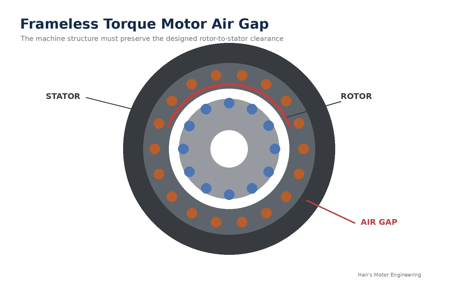

A frameless torque motor can meet every torque and speed requirement on paper and still fail after integration because of one mechanical detail that is easy to underestimate: the air gap. With a housed servo motor, the manufacturer controls the shaft, bearings, housing and the relationship between rotor and stator. With a frameless torque motor, the machine builder controls much of that final geometry. The air gap therefore becomes an integration requirement, not just a motor drawing dimension. There Is No Universal Air Gap The first mistake is looking for a generic air gap value before the motor has been selected. There is no universal number that can safely be applied across frameless torque motor families. The required gap is part of the electromagnetic design and depends on rotor diameter, magnet geometry, stator geometry, winding design and the intended operating point. The correct nominal air gap should come from the motor manufacturer's drawing. Deviating from that geometry changes the magnetic circuit. A smaller gap can increase flux density but can also leave insufficient mechanical clearance. A larger gap can reduce magnetic coupling and change torque production. Neither direction should be treated as an assembly adjustment unless the motor supplier has evaluated it. The useful engineering question is therefore not "What air gap should a frameless motor have?" It is "Can my machine maintain the specified air gap at every operating condition?"
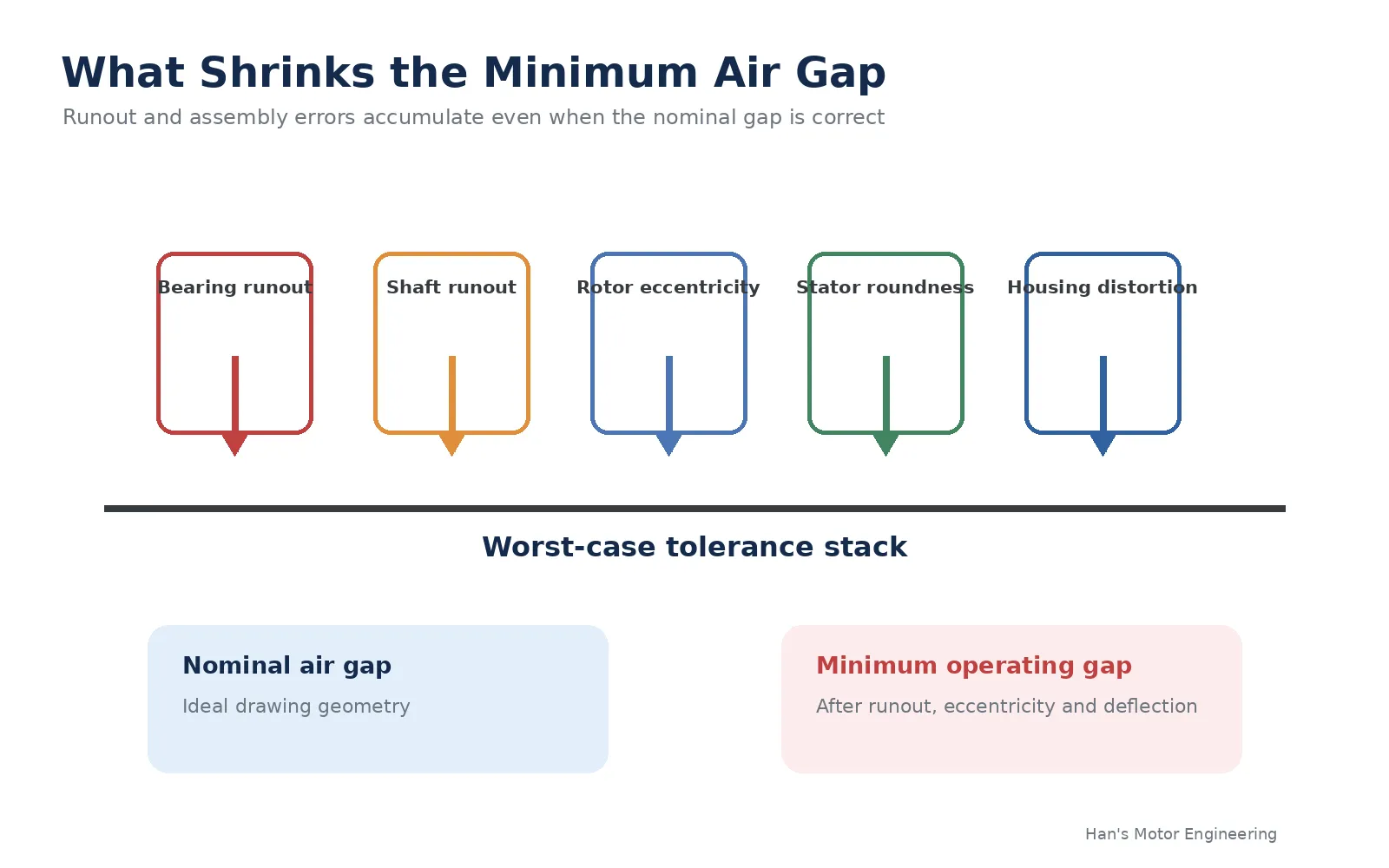
Nominal Gap Is Not Minimum Clearance The nominal gap assumes an ideal rotor and stator centered on the same axis. The real machine contains bearing runout, shaft runout, housing bore error, rotor eccentricity, stator concentricity error, assembly error, structural deflection and thermal growth. For a first pass, it is useful to think in terms of a clearance budget. Minimum operating clearance is approximately the nominal gap minus the radial effects of runout, eccentricity, bearing displacement, thermal growth and load induced deflection. The exact tolerance method can be worst case or statistical depending on the application, but the principle is the same. The design must be checked against the smallest local gap, not only the nominal dimension. This becomes especially important on large diameter torque motors. A small angular error or bearing displacement can create a meaningful local change in gap at the rotor perimeter even when the assembly looks well centered during a static inspection. The Bearing System Controls the Gap In a frameless motor, the bearings do more than support the application load. They establish the rotor position relative to the stator. Bearing radial runout, bearing seat accuracy, shaft geometry, preload and housing stiffness therefore become part of the motor tolerance stack. A bearing arrangement that is acceptable for a conventional geared axis may not be suitable for a high precision direct drive axis. This is one reason frameless torque motor integration should be reviewed together with the bearing concept rather than after the bearing design is already frozen. If you are integrating a motor into a robot joint, rotary table or gimbal, the HansMotor frameless torque motor integration guide is a useful starting point because bore size, bearing arrangement, rotor format and torque requirement are tightly linked. Stator Mounting Can Change the Gap The motor can lose concentricity before it ever turns. The stat
nt alignment as part of successful motor integration.
Thermal Expansion Belongs in the Tolerance Stack
A motor that is centered correctly at room temperature may not remain centered at operating temperature. The rotor shaft, bearings, housing and motor components can use different materials with different coefficients of thermal expansion. Temperature gradients can also be asymmetric, especially when one side of the housing has a better heat path than the other.
The direction of the gap change depends on the architecture, so a generic thermal safety factor is not enough. The relevant diameters, materials and temperature ranges should be evaluated at the expected cold and hot limits. High duty cycle machines should also consider transient thermal gradients rather than only the final steady state temperature.
Smaller Is Not Always Better
A smaller magnetic gap can improve magnetic coupling in a motor designed around that geometry, but that does not mean the integrator should intentionally position the rotor closer than specified. Once manufacturing tolerances and structural deflection are included, the theoretical electromagnetic gain can be outweighed by mechanical risk.
Rotor contact with the stator is the obvious failure mode. Before contact occurs, an uneven gap can also create unbalanced magnetic pull and nonuniform electromagnetic conditions. Depending on the motor design, that can make low speed behavior harder to control and can add load to the bearing system.
High precision direct drive is therefore not achieved by making the gap as small as possible. It is achieved by keeping the intended gap consistent.
Verify the Gap After Assembly
A frameless torque motor should not be accepted only by measuring the loose rotor and stator. The integrated axis is the finished motor. After assembly, the rotor should rotate through the complete mechanical range without contact, and the air gap should be checked around the full circumference using the inspection method recommended by the motor supplier.
Runout should be measured relative to the actual bearing axis, not an unrelated housing surface. If the machine experiences large payloads, high speed or significant temperature rise, the design should also be checked under representative operating conditions. A cold unloaded assembly can look perfect while the minimum gap changes under load or after thermal stabilization.
What Should Be Defined Before Ordering
For a custom frameless torque motor project, torque and speed are only part of the specification. The supplier should also understand the available stator outer diameter, required hollow bore, axial length, shaft and housing materials, bearing arrangement, expected runout, operating temperature, cooling method and proposed rotor and stator mounting methods.
Providing those inputs early allows the motor and the machine structure to be evaluated as one system. It also prevents a common late prototype problem where an electrically suitable motor is selected but the final bore, bearing layout or manufacturing tolerance leaves too little usable clearance.
Air Gap Is an Integration Requirement
The best air gap for a frameless torque motor is not a number copied from another motor's datasheet. It is the gap for which that specific electromagnetic design was developed, maintained by a mechanical structure capable of preserving it throughout the machine's operating envelope.
Bearing accuracy, concentricity, stator mounting, shaft runout, thermal expansion and structural deflection determine whether the nominal dimension on the drawing actually exists inside the finished machine. That is one of the central differences between buying a housed servo motor and integrating a frameless torque motor. Part of the motor engineering moves into the machine itself.



























Sign in to leave a comment.