Wiring a power module might seem like a straightforward task, but when accuracy and safety are on the line—especially with five-wire systems like the 29-5—precision becomes everything. A single misplaced connection could mean blown components, failed devices, or worse, an electrical hazard. That’s why a high-quality 29-5 power module wiring diagram isn’t just helpful—it’s critical.
Whether you're a technician, DIY enthusiast, or bulk electronics assembler, using a detailed, well-structured wiring diagram ensures every wire goes where it should. And when you're working on multiple setups or repairs, having a go-to visual guide is what separates smooth installations from frustrating rework. This article is your full tutorial on using the diagram the right way to reduce errors and improve long-term reliability.
The Importance of a High-Quality Wiring Diagram
When it comes to electrical wiring, especially for power modules like the 29-5, there is no room for trial and error. A high-quality wiring diagram serves as your blueprint—it maps out every connection, prevents common mistakes, and improves consistency, especially when doing repetitive tasks like installing multiple units.
Without a clear diagram, you risk:
- Swapping terminals
- Reversing polarity
- Missing the ground connection
- Creating electrical loops
All of these mistakes can destroy your device or pose safety hazards. The right diagram clears all that confusion, giving you a foolproof system to follow. Think of it as your personal safety net, especially when working in high-pressure environments where speed and accuracy both matter.
What Is a 29-5 Power Module? A Quick Overview
Before diving into the wiring, let’s clarify what a 29-5 power module actually is. This compact unit is designed to take AC input power and convert it into a stable DC output, making it ideal for modern electronics like LED TVs, small appliances, control systems, and DIY electronics.
The “29-5” label refers to:
- 29mm size format (depending on manufacturer design)
- 5-wire terminal layout, typically including:
- AC Live (L)
- AC Neutral (N)
- Ground (GND)
- +V DC Output
- –V DC Output
Simple enough on paper—but if you don’t wire these correctly, your entire setup can go wrong. That’s why relying on a detailed, accurate wiring diagram is essential.
High-Quality 29-5 Power Module Wiring Diagram: Why It Matters
Not all wiring diagrams are created equal. A high-quality version of the 29-5 power module wiring diagram stands out because it is:
- Clearly labeled
- Easy to follow
- Visually intuitive
- Accurate to real-world terminal positions
When you reference a poor-quality diagram, things get risky. Labels may be unclear, the wire colors may not match reality, and the entire layout can lead you down the wrong path. On the flip side, the right diagram—like the one provided by trusted sources—helps you wire faster and with greater confidence.
And in high-volume environments or repair centers, that means faster workflows and fewer failures.
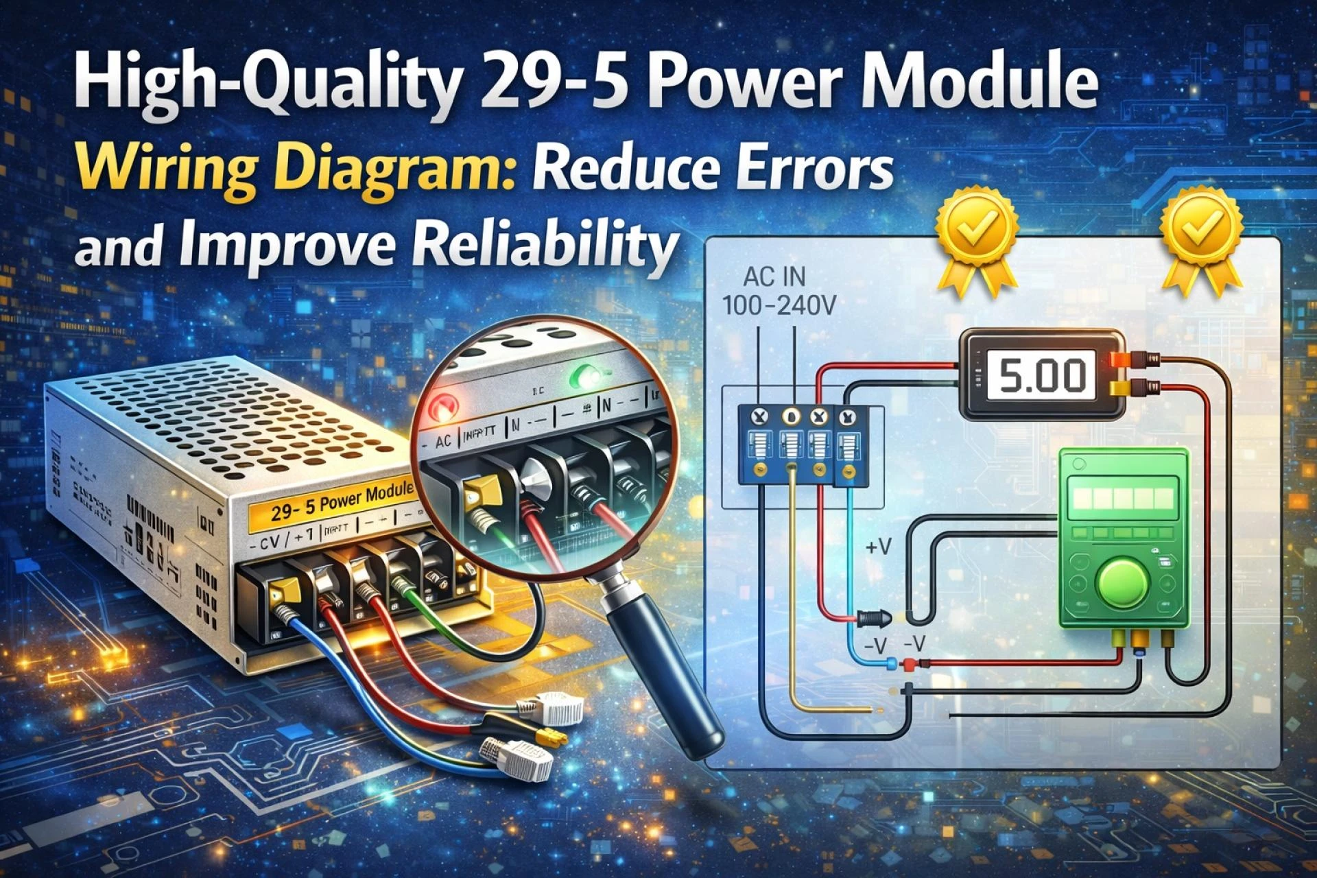
High-Quality 29-5 Power Module Wiring Diagram: Exploring the Five Wire System
The diagram available at this product link breaks down the five-wire layout in a user-friendly way. Let’s look at what those wires are and what they do:
- Live (L): Connects to your AC line power. Typically brown or red.
- Neutral (N): Connects to the AC neutral. Usually blue or black.
- Ground (GND): For safety—must be connected to avoid shocks.
- +V Output: Positive side of your DC power, sent to the powered device.
- –V Output: Negative return path for the DC circuit.
Each terminal on the diagram is marked and aligned exactly as it appears on the physical module, making your wiring job fast, accurate, and easy to verify.
Understanding the 5-Terminal Layout of the 29-5 Power Module
If you flip the module over or look at the side panel, you’ll see five screw or clip terminals. These correspond directly with the diagram. Understanding their layout helps you plan your wire placement and route cables for minimal clutter.
Typical layout from left to right:
- L → N → GND → +V → –V
By sticking to this order and referencing the diagram consistently, you eliminate guesswork. It's like having a color-by-numbers version of your electrical setup.
How a Precise Diagram Reduces Wiring Errors
Even experienced technicians can mess up when diagrams are missing or unclear. A high-quality wiring diagram helps you:
- Match wire colors to terminal labels
- Avoid switching positive and negative
- Spot missing ground connections
- Visually compare your setup before powering on
When you’re handling many units or installations, having that visual cue reduces mental load and keeps your process consistent. You’ll spend less time troubleshooting and more time getting things done right the first time.
Why Reliability Begins with Proper Wire Placement
Think of your wiring as the foundation of a house. If that foundation is shaky or sloppy, the whole structure is unstable. That’s why clean, accurate wire placement is so important—it ensures:
- Stable voltage delivery
- Lower risk of short circuits
- Improved lifespan for connected devices
- Fewer maintenance calls or failures
And yes, it all starts with a good diagram and following it to the letter.
Step-by-Step Installation Using the 29-5 Wiring Diagram
Let’s go through a quick step-by-step process using the high-quality wiring diagram:
- Power Off all inputs before starting.
- Strip your wires (approx. 1cm exposed copper).
- Connect L (Live) wire to terminal #1.
- Connect N (Neutral) to terminal #2.
- Connect GND (Ground) to terminal #3.
- Connect +V Output to terminal #4.
- Connect –V Output to terminal #5.
- Double-check each terminal against the diagram.
- Secure the wires with the terminal screws.
- Test with a multimeter before powering your device.
Tools Needed for a Clean and Reliable Setup
- Wire strippers
- Insulated screwdriver
- Multimeter (for voltage testing)
- Heat shrink tubing or electrical tape
- Wire labels or markers
- Mounting clips (for the module)
With these tools and the diagram at your side, you can install the 29-5 module like a pro.
Common Wiring Mistakes—and How to Avoid Them
Here are the top errors people make (and how to dodge them):
- Crossing +V and –V: Always double-check polarity.
- Leaving the Ground unconnected: This is a serious safety hazard.
- Loose terminals: Can lead to sparks or voltage drops.
- Incorrect AC input: L and N should never be reversed.
Following the diagram ensures you catch these issues before they become real problems.
Testing Your Connections Before Powering Up
Never plug your device in without testing:
- Use a multimeter to check DC output at the +V and –V terminals.
- Check continuity on the Ground terminal.
- Verify AC voltage is reaching the L and N terminals.
If the numbers are off, go back and review the diagram. Don’t guess—diagnose.
Real-World Uses of the 29-5 Power Module
This module shows up in all kinds of electronics:
- LED TVs and screens
- Home automation systems
- Security panels
- Audio amps and control circuits
- DIY robotics and maker projects
Each of these uses requires dependable power—which starts with correct wiring.
Troubleshooting Wiring Issues with the Help of a Diagram
If something doesn’t work:
- Refer back to the wiring diagram.
- Check each terminal and compare.
- Use your multimeter to identify missing voltage.
- Verify polarity is correct.
- Replace the module if wiring checks out and there’s no output.
The diagram turns troubleshooting into a checklist instead of a guessing game.
Final Thoughts: Why High-Quality Diagrams Lead to Better Builds
When you use a high-quality 29-5 power module wiring diagram, you're not just making installation easier—you’re ensuring safer, more reliable, and more professional builds. It reduces errors, speeds up work, and adds confidence to every wire you connect.
Whether you're wiring a single device or dozens in a production environment, having the right diagram in front of you is one of the smartest things you can do.
For full specifications, terminal layout, and the official wiring diagram, visit https://www.jhtledtvpcb.com/jht-power-module-5wire-29-5-product/


Sign in to leave a comment.