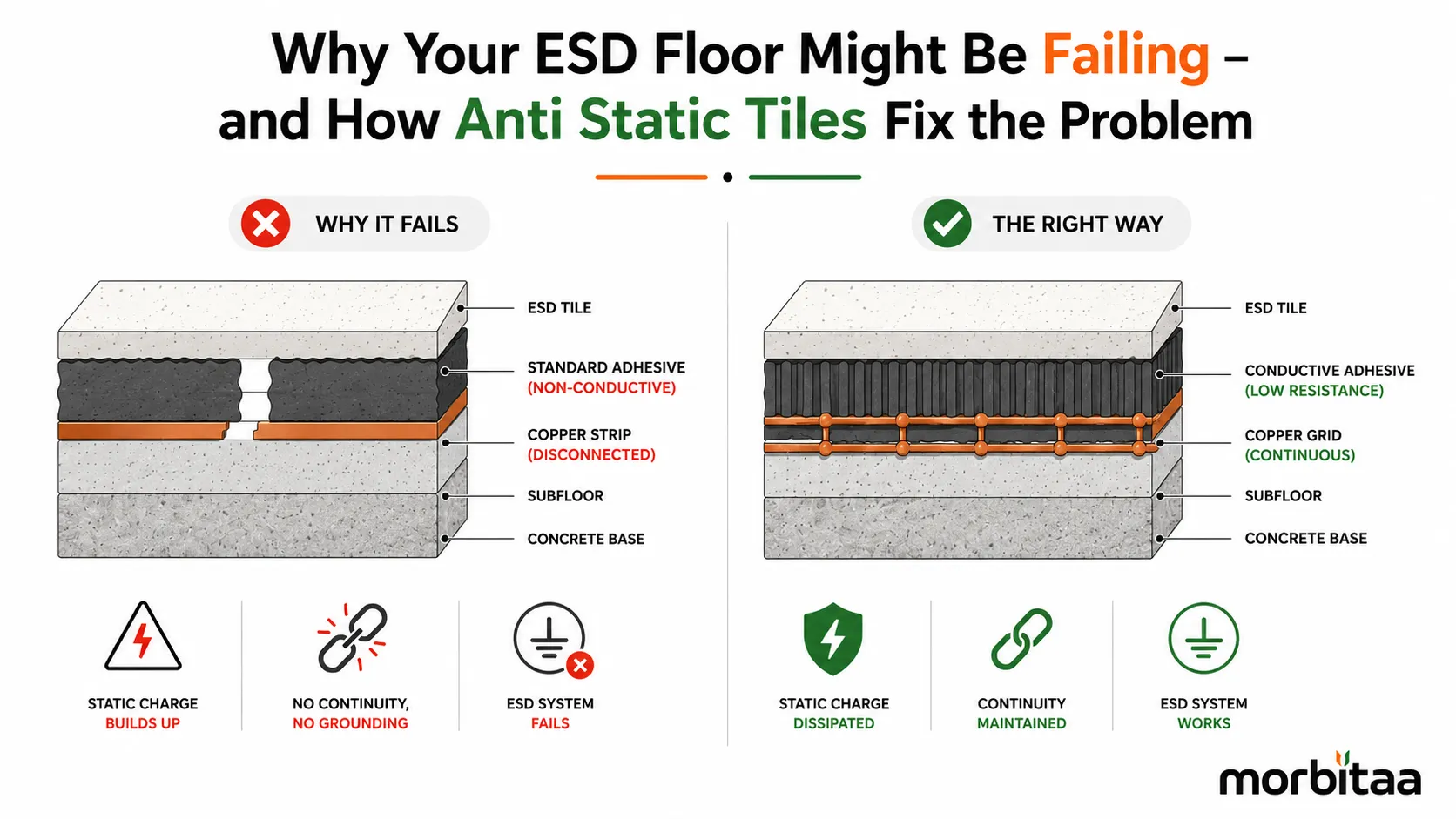

Picture this: a pharmaceutical cleanroom, freshly tiled with anti-static floor tiles, passes visual inspection. The copper grid was laid. The tiles are installed. Three months later, a routine compliance audit runs the megohmmeter and the floor fails.
The tiles were fine. The copper grid was fine. The adhesive was standard ceramic tile adhesive, bought because nobody on site confirmed the specification before the contractor ordered materials.
That one substitution, standard adhesive instead of ESD conductive adhesive, turned an entire floor installation into a very expensive standard tiled floor. No conductivity. No grounding path. Just a tile sitting on top of an electrical insulator.
This is the most common ESD floor failure pattern in India. And it's not the only one.
The Problem: Most ESD Failures Are Silent
Here's what makes ESD system failures so difficult to catch. They're invisible. A failed ESD floor doesn't look different from a working one. The tiles are laid flat. The finish looks good. The grout lines are clean.
But under the surface, one of these things has gone wrong. The adhesive isn't conductive, so the tile body has no electrical connection to the copper grid. Or the copper grid wasn't tied to the earth pit, so the charge has nowhere to go. Or the grout joints were filled with standard cement grout, which is electrically non-conductive and cuts the surface pathway between tiles. Or tile lots were mixed, creating zones with measurably different resistance values that show up inconsistently during testing.
Any one of these issues produces a floor that looks professional and fails the compliance test.
The Fix: Verify the System and Not Just the Tile
Specifying Anti Static Tiles from a manufacturer who provides batch-traceable surface resistance test certificates is step one. It eliminates the question of whether the tile itself meets the specification.
But the tile is only one component. The fix for a failing ESD floor, or the prevention of a future failure, is verifying every link in the grounding chain.
Check the adhesive specification. Standard IS 15477 adhesives are not ESD-grade. Conductivity must be confirmed directly with the adhesive manufacturer. If there's no separate conductivity certificate for the adhesive, it should not be used on an ESD floor.
Check the copper grid continuity. Every copper foil strip must run to the earth pit connection. A disconnected strip creates a dead zone that the megohmmeter will find. The grid should be tested before tiles go down, not after.
Check the grout type. Standard cement grout in an ESD floor breaks the conductive surface pathway at every joint. Conductive epoxy grout is the correct specification. It bridges the gap between tiles and maintains the continuous electrical surface.
Check the lot numbers. Mixed lot tiles create uneven resistance zones. Each lot may be individually compliant but produce inconsistent readings when combined across a floor area. One lot, one floor: that's the rule.
The Problem with "More Conductive is Safer"
One of the less-obvious failure modes in ESD flooring is specifying the wrong resistance range.
Static Dissipative tiles work for electronics manufacturing and server rooms. Conductive tiles are required for explosive-handling zones. But there's a lower boundary too. If a floor drops below 25,000 ohms, it becomes an electrocution hazard for workers operating near standard electrical equipment.
More conductive is not always safer. The resistance range needs to match the specific environment, the applicable compliance standard, and the actual risk profile of the space.
What a Compliant ESD Floor Looks Like
After correct installation with conductive adhesive, full copper grid continuity, conductive epoxy grout, same-lot tiles, and expansion joints at correct intervals, the floor-to-ground resistance test with a calibrated megohmmeter should return readings consistently within the specified range across all test points.
Document the result. ANSI/ESD S20.20 compliance requires ongoing ESD program records, and the post-installation test is the foundation of that file. Re-test quarterly in active facilities.
Any result outside range triggers a system investigation, not a visual inspection.
The floor that passes its audit is the one where every component of the grounding chain was verified, not assumed.





























Sign in to leave a comment.