Introduction to USB technology
Introduction to USB 2.0
USB 2.0 is a high-speed serial input bus that supports hot swapping. It uses differential signals to transmit data, with a maximum speed of up to 480Mb/s. When powered by USB 2.0, devices can receive a minimum of 500mA of current. A USB 2.0 cable typically consists of a total of 4 conductors (as shown in Figure 1); among them, the D+ and D- ports are used to transmit USB 2.0 data, VBus is the power line, and GND is the ground wire.
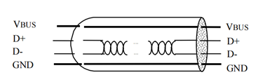
Figure.1
The USB system defines four types of transfers:
- Control Transfer: Primarily used for device enumeration when a device is connected and for other specific device operations.
- Interrupt Transfer: Used for reliable transmission of small amounts of data with strict latency requirements, such as for keyboards, game controllers, and similar devices.
- Bulk Transfer: Used for reliable transmission of large amounts of data with relaxed latency requirements, like for USB flash drives.
- Isochronous Transfer: Used for real-time data transmission with less stringent reliability requirements, such as for webcams and USB speakers.
These different transfer types don’t have significant differences at the physical layer but vary in terms of transfer mechanisms, how the host schedules transfers, limitations on USB bandwidth utilization, and maximum packet lengths.
Introduction to USB 3.0
USB 3.0 is a physical, high-speed bus that operates in parallel with a physical USB 2.0 bus. It shares a similar architectural framework with USB 2.0. USB 3.0 cables have eight main conductors: three twisted pairs for USB data pathways and one pair for power (as shown in Figure 2). In addition to the twisted pairs required for USB 2.0 data pathways, there are two additional twisted pairs used to provide the SuperSpeed data pathways, one for transmission and one for reception.
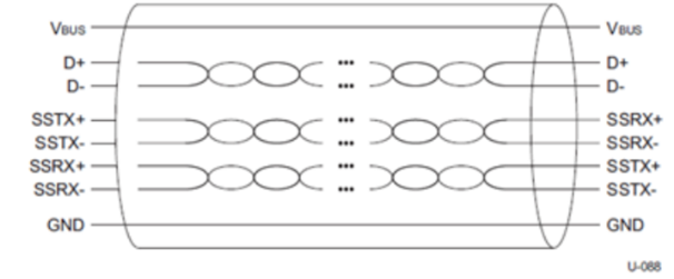
Figure 2
The USB 3.0 specification defines the following connectors:
USB 3.0 Standard-A plug and receptacle; USB 3.0 Standard-B plug and receptacle; USB 3.0 Powered-B plug and receptacle; USB 3.0 Micro-B plug and receptacle; USB 3.0 Micro-A plug; USB 3.0 Micro-AB receptacle ; USB 2.0/3.0 plugs as shown in Figure 3 ;
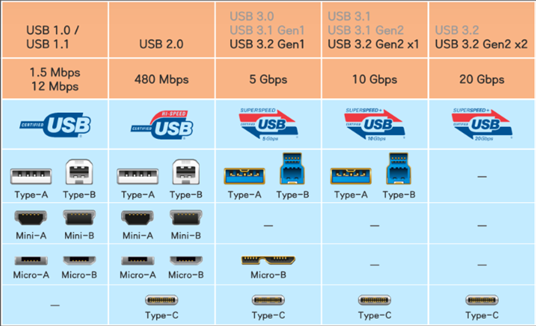
Figure 3
Main Differences Between Different USB Versions
USB 2.0 and USB 3.0:
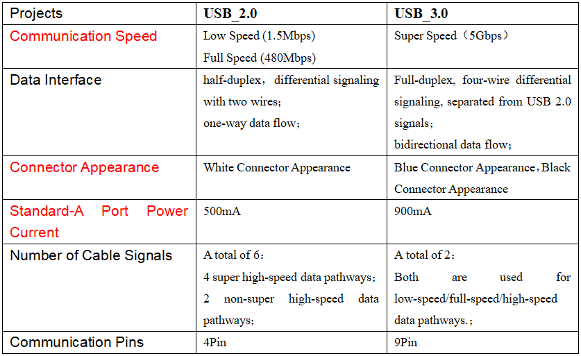
Table 1(Note: The red part is the main difference.)
Difference between USB 2.0 and USB 3.0:
There is a significant improvement in the protocol optimization from USB 2.0 to USB 3.0. The main difference lies in the fact that USB 3.0 employs a dual-bus architecture, integrating both the USB 2.0 bus and the super-speed bus. This allows USB 3.0 to be backward compatible with USB 2.0 data transfer while introducing the advantages of the super-speed bus. It serves as the foundation for subsequent developments, including USB Type-C, which builds upon the USB 3.0 architecture.
It’s also important to note differences in power supply current and connector appearance. For differences in power supply current, please refer to section 2.2 on USB power supply current. As for connector differences, the primary distinction is in the color: USB 3.0 specifications require a blue connector (Pantone International Color Card 300C). The table below outlines the differences between USB 3.x versions, mainly focusing on bandwidth and encoding variations, which are not as distinct as the transition from USB 2.0 to 3.0.
Differences between USB 3.x and subsequent series:
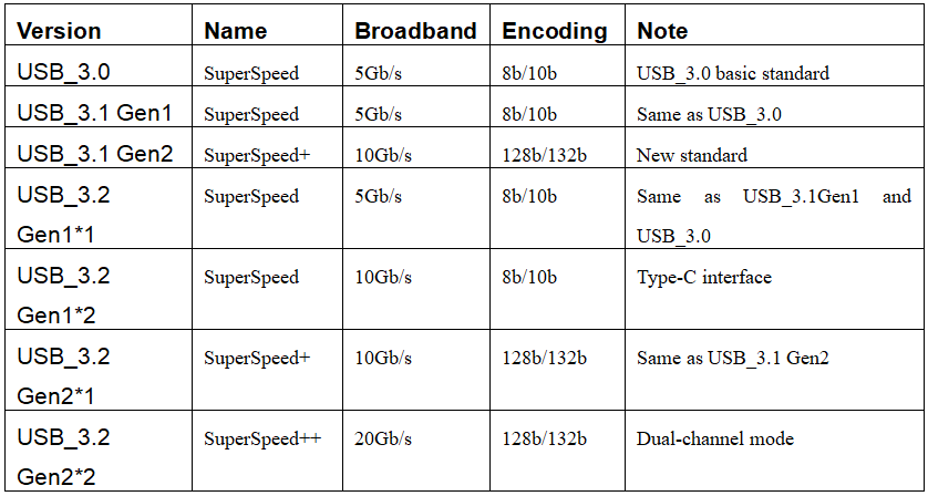
Table 2
Differences between USB 3.0 and USB 3.1:
- Speed Enhancement: USB 3.1 provides a speed increase from 5 Gbps (in USB 3.0) to 10 Gbps.
- Increased Power Delivery: USB 3.1 supports a maximum power delivery of 100W, with higher voltage and current.
- Addition of Type-C Connector: USB 3.1 introduced the Type-C connector, which is reversible and versatile.
- Reduced Encoding Overhead: USB 3.1 reduced encoding losses by shifting from 8b/10b encoding to 128b/132b, decreasing encoding overhead from the original 20% to 3%.
Differences between USB 3.1 and USB 3.2:
- Speed Boost: USB 3.2 further increases data transfer speeds from 10 Gbps (in USB 3.1) to 20 Gbps.
- Dual-Channel Design: USB 3.2 Gen2*2 employs a dual-channel design, requiring the use of Type-C cables for optimal performance.
USB Considerations and Solutions in the Commercial AV Market
Cascading Levels and Maximum Number of Connected Devices Between USB Devices
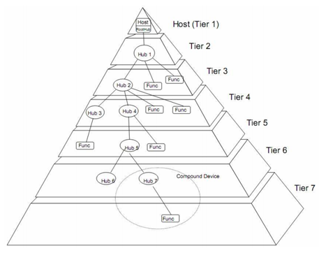
Figure 4
In engineering design, there can be issues related to the cascading levels of USB devices, where too many levels can lead to USB devices not functioning correctly. For example, when a camera serves as the signal source, and it is used a scheme involving more than 5 levels of cascaded HUBs, which will result in abnormal operation of the camera device, causing confusion for engineers. Similar issues can arise with other devices.
Here’s a detailed explanation of the concept and principles of USB cascading levels:
USB is a comprehensive system that comprises three main components: “Host,” “Device,” and “Physical Connection.” The host is a composite of hardware, software, and firmware that provides USB interfaces and interface management capabilities. Due to the inherent limitations of this system, the concept of cascading levels has emerged (illustrated in Figure 4).
For USB 2.0 devices, the protocol specifies that a USB host can connect to a maximum of 127 Device devices (wherein intermediate USB Hubs count as devices). Furthermore, the maximum allowed levels of USB Hubs between the USB host and Device is limited to 5.
For USB 3.0 devices, the protocol stipulates that a USB host can connect to a maximum of 63 Device devices (with intermediate USB Hubs counted as devices). Similarly, the maximum allowed levels of USB Hubs between the USB host and Device are limited to 5.
The limitation on the number of levels for USB Hubs primarily arises from the strict time constraints imposed on packet reception between the HOST and DEVICE. When packet reception times exceed these constraints, the system may no longer respond reliably. As the number of Hub levels increases, the response time also lengthens, leading to a restriction on the number of levels. In engineering applications, if a device incorporates a USB Hub internally, it must be included in the evaluation of the system’s connectivity. Typically, integrated components such as all-in-one touchscreens may have 1–2 levels of internal USB Hubs, and KVM switches, extenders, and matrices may also have 1–2 levels of built-in Hubs.
USB Hub Cascading in USB Extenders
AV Access offers two categories of USB-related products: KVM extenders and KVM switches. In practical engineering applications, it is preferable to minimize the number of USB levels between the computer host and the devices.
AV Access currently offers two types of KVM extender solutions:
KVM extenders occupy only one level of HUB (with this level of HUB connected internally to the RX). If users need to connect more devices and want better product performance, they can choose a device that uses a USB HUB occupying only one level. Please refer to the following options:
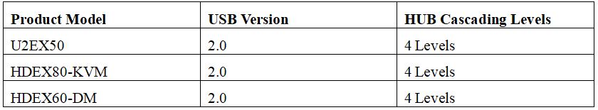
Table 3
KVM extenders use 4 levels of HUBs (3 levels for the extender and an additional built-in HUB in the device, which is connected internally to the RX). While these products have a higher number of USB HUB levels, they come with sufficient USB Device interfaces for users. If more interfaces are needed, an external HUB can be added, allowing for the connection of over 20 USB devices. This should be adequate for most users. This type of product is generally more affordable. If peripheral connections are relatively stable, you can consider purchasing the following equipment. Optional devices are as follows:
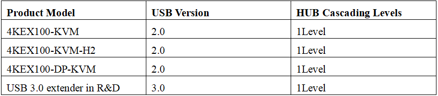
Table 4
For KVM switch devices, they typically use only 1–2 levels of USB HUB, which generally doesn’t pose issues for engineering applications.
USB Power Supply
For devices that rely on USB power, such as USB cameras or other USB devices, it’s important to pay attention to the current supplied by the Device A port. According to the standard specifications, USB 2.0 requires a minimum power supply of 500mA, and USB 3.0 requires a minimum power supply of 900mA.
USB Cable Length
In the USB protocol, there are regulations regarding the maximum length of USB 2.0 cables, which is set at 4 meters. With high-quality cables, USB 2.0 cables can sometimes extend up to 5 meters, but for reliability, it’s best to use compliant cables and try to stay under 4 meters.
For USB 3.0, if we consider the full-speed 5Gbps transfer rate of USB 3.2 Gen1, the standard specifies a maximum length of 2 meters. With high-quality cables, USB 3.0 cables can sometimes extend up to 3 meters, but for reliability, it’s best to use compliant cables and try to stay under 2 meters. Of course, if the actual transfer rate is lower, you may be able to use longer cables.
In engineering applications, shorter cables provide more guaranteed speed. If longer cables are necessary, their feasibility should be tested in practice, and this also depends on the speed requirements of the devices involved. Some special custom cables may exceed the conventional length limits mentioned above.
Source: https://www.avaccess.com/blogs/guides/introduction-to-usb-technology/