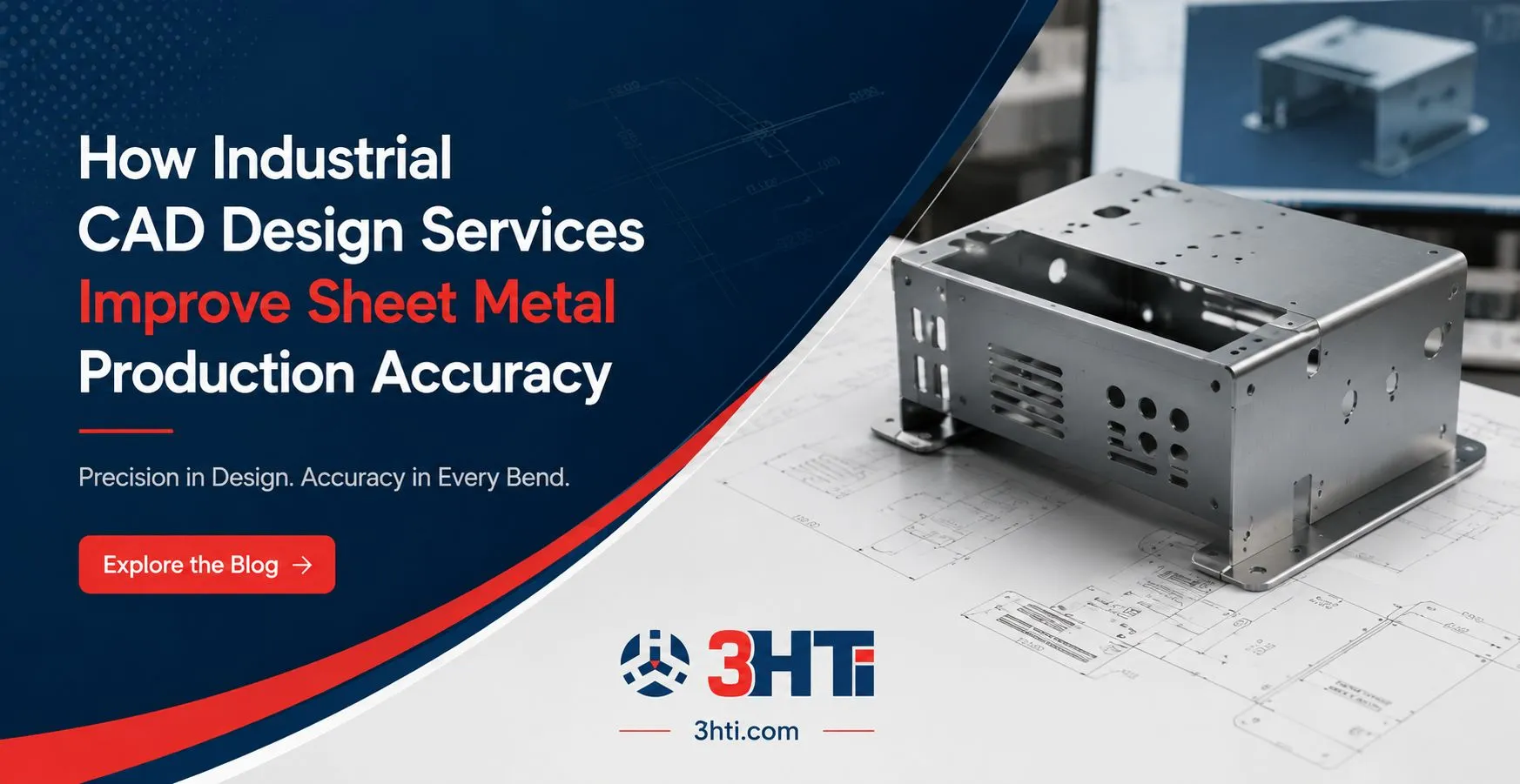

Sheet metal production leaves little room for ambiguity. A small error in bend allowance, hole placement, material thickness, bend relief, or flat-pattern geometry can propagate from a digital model to tooling, fabrication, inspection, and final assembly. CAD design services improve sheet metal production accuracy by converting manufacturing requirements into controlled, production-ready digital models and drawings before material reaches the shop floor.
For engineering organizations managing complex product portfolios, the value extends beyond geometry. Properly structured CAD models support design-for-manufacturing (DFM), tolerance management, product data consistency, simulation, and downstream product lifecycle management (PLM).
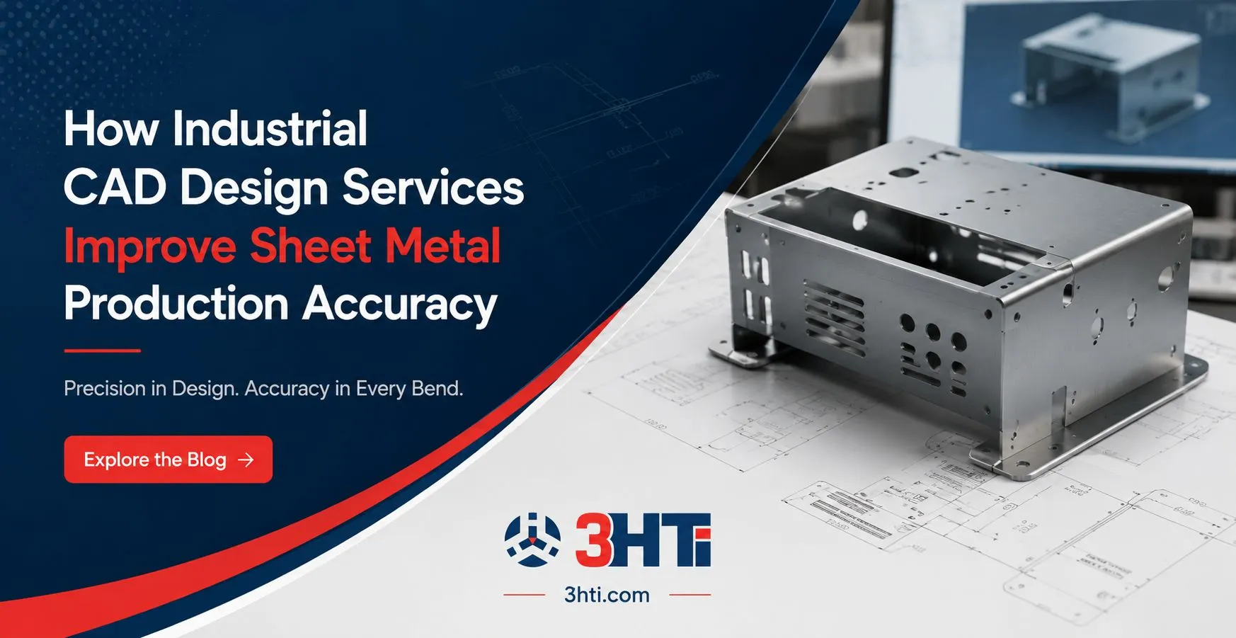
What Are CAD Design Services for Sheet Metal?
CAD design services are professional engineering services that create, modify, validate, and document computer-aided design models for manufacturing. For sheet metal production, their primary function is to ensure that 3D geometry, bend features, flat patterns, tolerances, drawings, and manufacturing requirements remain consistent.
They matter because production accuracy depends on more than a visually correct model. A manufacturing-ready design must account for material behavior, bend sequences, tooling constraints, tolerances, joining methods, and inspection requirements.
Common applications include:
- Sheet metal enclosure and chassis design
- Brackets, panels, frames, and structural components
- Flat-pattern development
- Bend relief and bend allowance definition
- Design-for-manufacturing reviews
- Geometric dimensioning and tolerancing (GD&T)
- Assembly interference and clearance checks
- Legacy drawing modernization
- CAD-to-PLM data integration
Why CAD Design Services Improve Sheet Metal Accuracy
The strongest CAD workflows prevent manufacturing problems during design rather than discovering them after fabrication.
1. Accurate 3D Geometry Controls Downstream Manufacturing
A properly constrained parametric model establishes relationships between dimensions, features, and design intent. When engineers change material thickness or a critical dimension, dependent features can update systematically rather than requiring disconnected manual edits.
This becomes especially valuable for configurable products with multiple sizes or variants.
Professional 3D CAD modeling services can also establish standardized modeling practices, naming conventions, feature structures, and drawing methods across engineering teams. The result is greater consistency when multiple designers contribute to the same product family.
2. Flat Patterns Connect Design Intent to Fabrication
A sheet metal model must eventually become a manufacturable flat pattern. Incorrect bend allowances, reliefs, or unfolding assumptions can produce dimensions that look correct in the 3D environment but fail during fabrication.
A production-oriented CAD workflow therefore validates:
- Material thickness and material specification
- Bend radius
- Bend allowance or bend deduction methodology
- Bend relief
- Hole-to-bend distances
- Corner conditions
- Flat-pattern dimensions
- Manufacturing sequence constraints
The important distinction is that unfoldability is a manufacturing requirement, not simply a CAD feature.
3. DFM Reviews Reduce Expensive Design Rework
Design-for-manufacturing evaluates whether a component can be produced consistently using the intended process.
For sheet metal, a DFM review may identify a bend that conflicts with tooling, a hole positioned too close to an edge, an unnecessarily tight tolerance, or a geometry requiring an inefficient fabrication operation.
A strong engineering team addresses these issues before tooling, cutting, forming, or finishing begins. This shifts corrective action upstream, where design changes are generally easier to control.
How the CAD-to-Production Workflow Should Work
Accuracy improves when CAD data follows a controlled engineering workflow rather than moving through disconnected files.
Step 1: Establish Manufacturing Requirements
Define material, thickness, fabrication method, tooling limitations, tolerances, finishing requirements, and inspection criteria before modeling begins.
Step 2: Build Parametric Geometry
Create the model using controlled features and relationships. Avoid unnecessary geometry that makes future revisions difficult.
Step 3: Validate Manufacturability
Review bends, reliefs, clearances, hole locations, tooling access, tolerance requirements, and assembly interfaces.
Step 4: Generate Production Documentation
Create manufacturing drawings, GD&T annotations, flat patterns, bills of material, and other required documentation.
Step 5: Review and Release Through PLM
Approved CAD data should enter the organization's controlled product data environment. PLM managed services can help maintain revision control, workflows, access permissions, and relationships between engineering data and lifecycle processes.
This final step matters because production accuracy can be undermined by using an outdated drawing even when the original CAD model was correct.
Where FEA Fits Into Sheet Metal Design
Finite element analysis (FEA) should be used when structural behavior requires engineering validation beyond geometric inspection.
For example, a sheet metal enclosure may need evaluation for deformation, stress, vibration, or loading conditions. FEA simulation services can help engineers assess whether a design meets defined performance requirements before physical prototypes are manufactured.
However, simulation should not replace basic CAD discipline. A poorly defined geometry or incorrect material assumption can produce misleading analytical results. The model must first represent the intended physical design accurately.
CAD Design Services vs. Internal-Only Modeling
Organizations do not necessarily need to outsource every CAD activity. The better question is where specialized CAD support creates measurable engineering value.
Internal teams often have the strongest understanding of product architecture and engineering intent. External CAD specialists can provide additional capacity for:
- Large modeling backlogs
- Legacy data conversion
- Production drawing updates
- Complex sheet metal detailing
- Design standardization
- CAD platform transitions
- Temporary engineering workload peaks
The strongest model is often a controlled team extension rather than a complete replacement of internal engineering capability.
3HTi, for example, describes its CAD offering as spanning 3D modeling, sheet metal design, GD&T, design optimization, DFM, reverse engineering, and CAD integration across multiple platforms. Organizations evaluating this type of support can review its CAD design services in the context of their own engineering workflow.
Common CAD Mistakes That Reduce Production Accuracy
Several problems repeatedly create downstream manufacturing issues:
Modeling without manufacturing input: Engineers may create technically valid geometry that is difficult or expensive to fabricate.
Over-tolerancing: Applying unnecessarily tight tolerances can increase manufacturing and inspection costs without improving functional performance.
Weak revision control: Multiple copies of drawings and models can result in fabrication from obsolete information.
Manual flat-pattern changes: Editing unfolded geometry independently from the master model can break design intent.
Poor feature organization: Unstructured parametric models make engineering changes slower and more error-prone.
Ignoring downstream systems: CAD data that is not properly connected to PLM can create traceability and revision-management problems.
Connecting CAD Accuracy With Digital Transformation
CAD accuracy becomes more valuable when engineering data participates in a broader digital product lifecycle.
Digital transformation services companies increasingly connect CAD, simulation, PLM, manufacturing, requirements, and other engineering systems into a more controlled digital thread. This allows design changes to propagate through governed processes instead of relying on email attachments and manually maintained spreadsheets.
For an enterprise, the objective is not simply to create a more accurate sheet metal model. It is to establish a repeatable chain from engineering intent → validated geometry → manufacturing definition → controlled release → production.
How to Choose the Right CAD Support Model
Before engaging CAD design services, engineering leaders should evaluate:
- Manufacturing expertise: Does the provider understand sheet metal fabrication rather than only CAD software?
- Platform capability: Can the team work within the organization's existing CAD environment?
- PLM compatibility: Can engineering data follow existing product data and revision processes?
- Documentation quality: Are drawings, GD&T, BOMs, and flat patterns included?
- Scalability: Can support expand during engineering peaks?
- Quality controls: Are peer reviews and design validation built into delivery?
- Data security: Are proprietary models and engineering documentation handled appropriately?
The right provider should fit the engineering process rather than force the organization to redesign its workflow around the service.
Conclusion
Industrial CAD design services improve sheet metal production accuracy by controlling the relationship between geometry, manufacturing requirements, documentation, simulation, and product data. The greatest gains occur when manufacturability is considered during modeling rather than after fabrication problems appear.
For complex manufacturing organizations, accurate CAD is only one component of the equation. Parametric modeling, DFM, GD&T, FEA, PLM governance, and controlled revision management must work together to create reliable production definitions.
The practical objective is straightforward: make the digital definition accurate enough, complete enough, and controlled enough that manufacturing does not have to reinterpret engineering intent.
FAQs
How do CAD design services improve sheet metal manufacturing?
CAD design services improve manufacturing accuracy by validating geometry, bend conditions, flat patterns, tolerances, clearances, and production documentation before fabrication. They also help standardize modeling practices and reduce discrepancies between engineering models and manufacturing drawings.
Why is 3D CAD modeling important for sheet metal?
3D CAD modeling provides a structured representation of the finished component while maintaining relationships between dimensions and features. Parametric modeling allows controlled design changes and supports flat-pattern generation, assembly checking, documentation, and downstream PLM processes.
What is DFM in sheet metal design?
Design for manufacturing (DFM) evaluates whether a design can be produced efficiently and consistently using the intended manufacturing process. For sheet metal, DFM commonly considers bends, tooling access, material thickness, reliefs, tolerances, holes, and fabrication constraints.
Can FEA be used for sheet metal components?
Yes. FEA can evaluate structural behavior such as stress, deformation, vibration, or loading when analytical validation is required. Its usefulness depends on accurate geometry, material properties, boundary conditions, and appropriate modeling assumptions.
How does PLM support CAD accuracy?
PLM provides controlled management of CAD files, revisions, relationships, approvals, and product information. This helps prevent obsolete models or drawings from reaching manufacturing and creates greater traceability around engineering changes.
When should a company use external CAD design services?
External CAD support is useful when organizations face modeling backlogs, specialized sheet metal requirements, legacy-data work, platform transitions, or temporary capacity constraints. It can supplement internal engineering without replacing product knowledge held by internal teams.
What should manufacturing companies check before outsourcing CAD work?
Companies should assess CAD platform expertise, manufacturing knowledge, documentation standards, PLM compatibility, quality controls, data security, scalability, and communication processes. A technically capable CAD provider may still be unsuitable if its workflow does not align with the company's engineering controls.





























Sign in to leave a comment.