Introduction
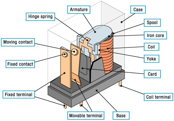
A relay is an electrical control device. It makes the controlled quantity to undergo a predetermined step change in the electrical output circuit when the input quantity (excitation quantity) changes to the specified requirements. Electrical relay has an interactive relationship between the control system (also called the input loop) and the controlled system (also called the output loop).
Usually used in automated control circuits, it is actually an “automatic switch” that uses a small current to control the operation of a large current. Therefore, it plays the role of automatic adjustment, safety protection, and conversion in the circuit. So how can we wire the relay to play its role in the circuit?
Relay Wiring with Different Pins
3 Pin Relay
1) What is 3 Pin Relay?
A 3 pin relay works on principles of electromechanics to appropriately power turn and hazard signals on most automobiles manufactured.
2) How to Wire 3 Pin Relay?
Fig 1. 3 Pin Relay Wiring Diagram
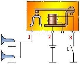
The common 3 pin relay is the car horn relay.
1 is the contact terminal, which is connected to the load.
2 is the common terminal of the contact and the coil, which is connected to the power supply.
3 is the coil terminal, which is connected to the button switch (such as the horn button on the steering wheel).
When press the button, 2 and 3 are turned on, the coil is energized, the contacts are closed, 1 and 2 are turned on, and the horn emits a sound.
4 Pin Relay
1) What is 4 Pin Relay?
A 4 pin relay is always used to control a single circuit.
2) How to Wire 4 Pin Relay?
Fig 2. 4 Pin Relay Wiring Diagram
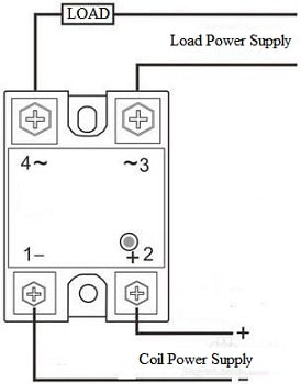
The 4-pin relay is the most common single-pole single-throw relay.
Pin 1 and pin 2 are coil terminals, and pin 3 and pin 4 are contact terminals.
1 and 2 are on, the coil is energized, having internal mechanical transmission, 3 and 4 contacts are closed (normally closed type is open), and the load circuit is on.
Example:
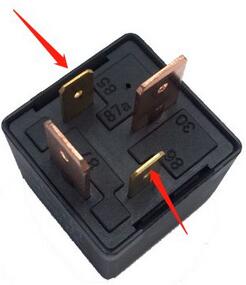
Fig 3. 12V 40A 4 Pin Relay
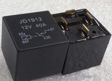
1) Look at the two terminals 85 and 86, from the side structure diagram, we can know that these two are used to control electromagnetic attraction and disconnection. So one is often connected to the positive pole of the power supply and another end is connected the low-side drive output pin.
Fig 4. Pins (85 & 86)
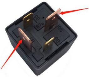
2) Look at the two terminals are pins 30 and 87 respectively, of which pin 30 is the normally closed contact and pin 87 is the normally open contact. According to circuit requirement, pin 30 is also connected to the positive pole of the power supply, pin 87 is connected to one side of the load, and the other side of the load is grounded.
Fig 5. Pins (30 & 87)
5 Pin Relay
1) What is 5 Pin Relay?
A 5 pin relay is always used to switch power between two circuits. It has two to operate the coil and three for the switch to incorporate a common single-pole double-throw function.
2) How to Wire 5 Pin Relay?
Fig 6. 5 Pin Relay Wiring Diagram
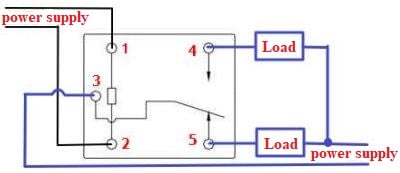
1, 2 are coil terminals, 3 is a common contact, 4 and 5 are normally open and normally closed contacts respectively.
In the initial state, contacts 3 and 5 are turned on, and load 5 works. After the coil power is supplied, 1 and 2 are turned on, the coil is energized, and the common contact of 3 is switched to closed with the normally open contact 4, and load 4 starts to work.
6 Pin Relay
1) What is 6 Pin Relay?
6 pin relay is an important element of the electricity system.
2) How to Wire 6 Pin Relay?
Fig 7. 6 Pin Relay Wiring Diagram
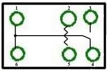
The principle of conventional 6-pin relay is closed to the 5-pin, that is, there is one more common terminal. Two terminals 1, 6 are connected together and used as common terminals at the same time.
8 Pin Relay
1) What is 8 Pin Relay?
8 pin relay is a double pole double throw (DPDT) structure. Its two middle contacts are connected to the motor, the two ends of the contacts are connected to the power supply and the ground wire, and the normally open contacts are connected to the positive and the negative, and the normally closed contacts are connected to the negative and the positive.
2) How to Wire 8 Pin Relay?
Fig 8. 8 Pin Relay Wiring Diagram
The internal circuit of a conventional 8-pin relay is shown in the following figure. 2 and 7 are coil terminals, and the remaining terminals form two sets of single-pole double-throw, and the connection of each group is the same as that of the 5-pin relay.
No matter energized or de-energized, the coil simultaneously controls the switching of two sets of single-pole double-throw switches.
Intermediate Relay
1) What is Intermediate Relay?
Intermediate relays are usually used to transmit signals and control multiple circuits at the same time, and can also be used to directly control small-capacity motors or other electrical actuators. The structure and working principle of it are basically the same as the AC contactor. However, its contacts and their capacity are large than ac contactor.
2) How to Wire Intermediate Relay?
Each intermediate relay is marked with the voltage level and wiring method, generally the 13 and the 14 are connected to the coil, and the remaining four groups of contacts can be connected according to the label. Among them, 13 and 14 are the coil pins of the relay, which are used to connect to the control power supply. The intermediate relay controls the opening and closing of the contacts by controlling whether the coil is energized or not. 1, 5, 9; 2, 6, 10; 3, 7, 11; 4, 8, 12 are four sets respectively, of which 1, 2, 3, 4 are the common terminals of the contacts; 5, 6, 7, 8 is the normally closed contacts; 9, 10, 11, 12 are the normally open contacts.
Example:
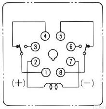
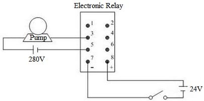
Fig 9. Intermediate Relay Wiring Diagram
5 and 6 are a pair of common terminals, 1 and 2 are a pair of normally closed contacts, and 3 and 4 are a pair of normally open contacts. When 7 and 8 are not energized, 5-6 and 1-2 are connected, and 1-2 will be disconnected after power-on, and 5-6 will be continuously connected, and then connected with 3-4.
Generally, the intermediate relay is a double-pole double-throw switch. The 7-8 terminals are connected to the internal coil. A freewheeling diode is connected in parallel when used. The polarity of the diode is opposite to that of the relay terminal (8+ is connected to the cathode and 7- is connected the positive pole of the diode).
When the predetermined value is reached, the relay will work and the drive circuit will be disconnected. At that moment, a high current will be generated due to the self-inductance voltage, and this current will flow through the freewheeling diode instead of passing through the circuit, thereby protecting the components in the circuit.
No matter how many pins the relay has, they all belong to two basic types and combinations of SPST (single pole single throw) and SPDT (single pole double throw). According to their internal wiring diagrams, external wiring is simple.
If you have any interest, get full details from Electrical Relay Wiring Methods.