Disclaimer: This is a user generated content submitted by a member of the WriteUpCafe Community. The views and writings here reflect that of the author and not of WriteUpCafe. If you have any complaints regarding this post kindly report it to us.
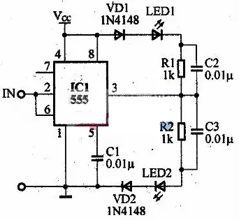 This circuit makes use of the setting and resetting characteristics of the trigger end 2 pin and the threshold 6 pin of the 555 circuit to form a test pen for detecting whether the digital logic state is normal. Suppose that when the probe IN input is low level “0”, LED2 is on, and when high level “1” is input, LED1 is on. R1, C2 and R2, C3 networks are accelerated networks. This logic pen is suitable for testing digital circuits such as TTL and CMOS. When measuring, make this circuit and the circuit under test common ground.