1. Introduction
In today’s high-density data centers and hyperscale environments, every fraction of a watt and millimeter of cable length matters. As operators push for higher port densities and lower latency, the choice of interconnect—copper or optical—has significant cost and performance implications. Direct Attach Copper (DAC) cables have long occupied a niche for very short-reach, high-speed links (e.g., server-to-switch or switch-to-switch within a rack). This article explores DACs from the ground up: how they’re constructed, how they compare to optical solutions, common use cases, breakout options, practical deployment guidelines, and where the technology is headed as Ethernet speeds climb beyond 100 Gbps.
2. Definition and Physical Structure of DAC Cables
What “Direct Attach” Means
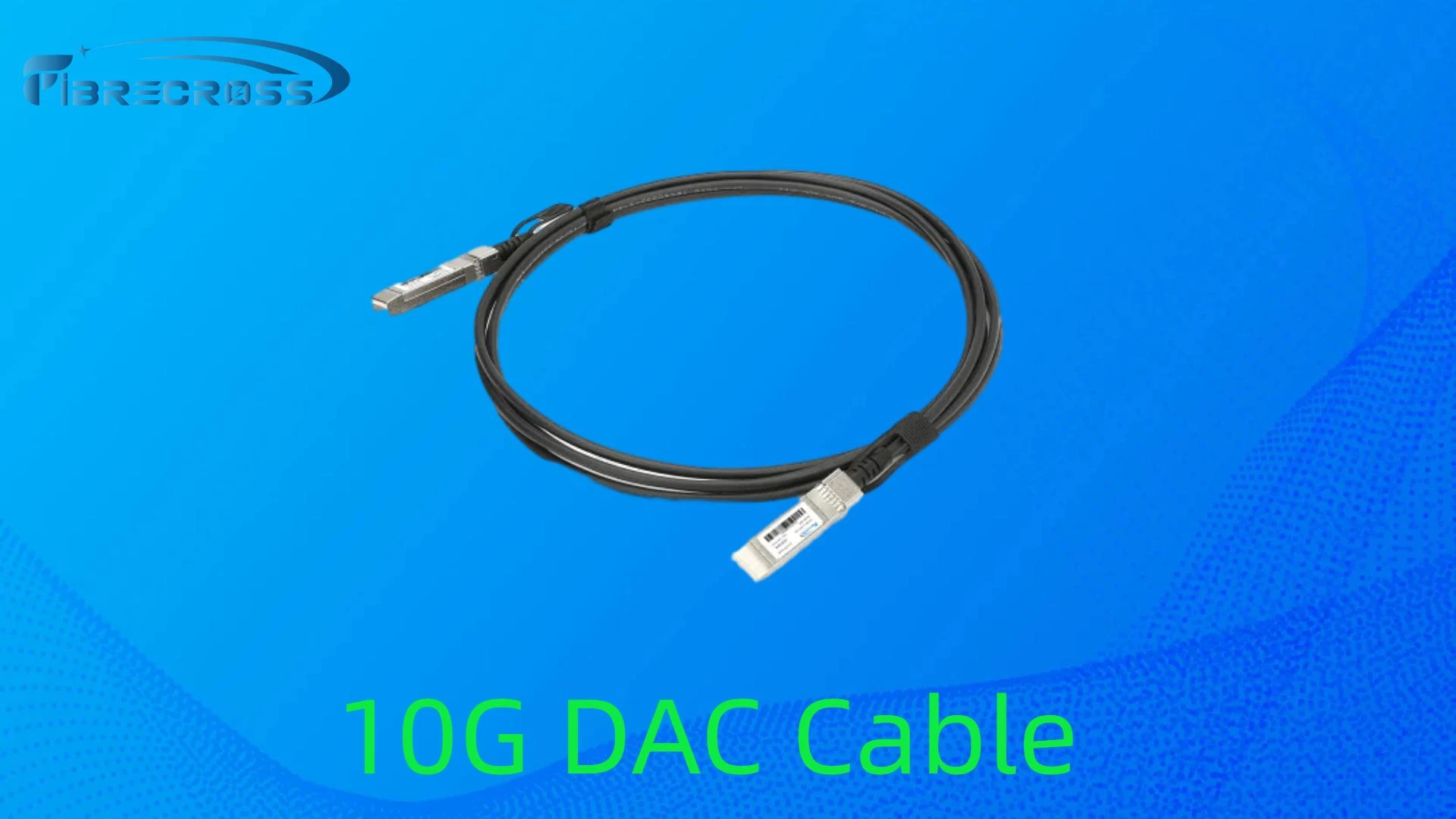
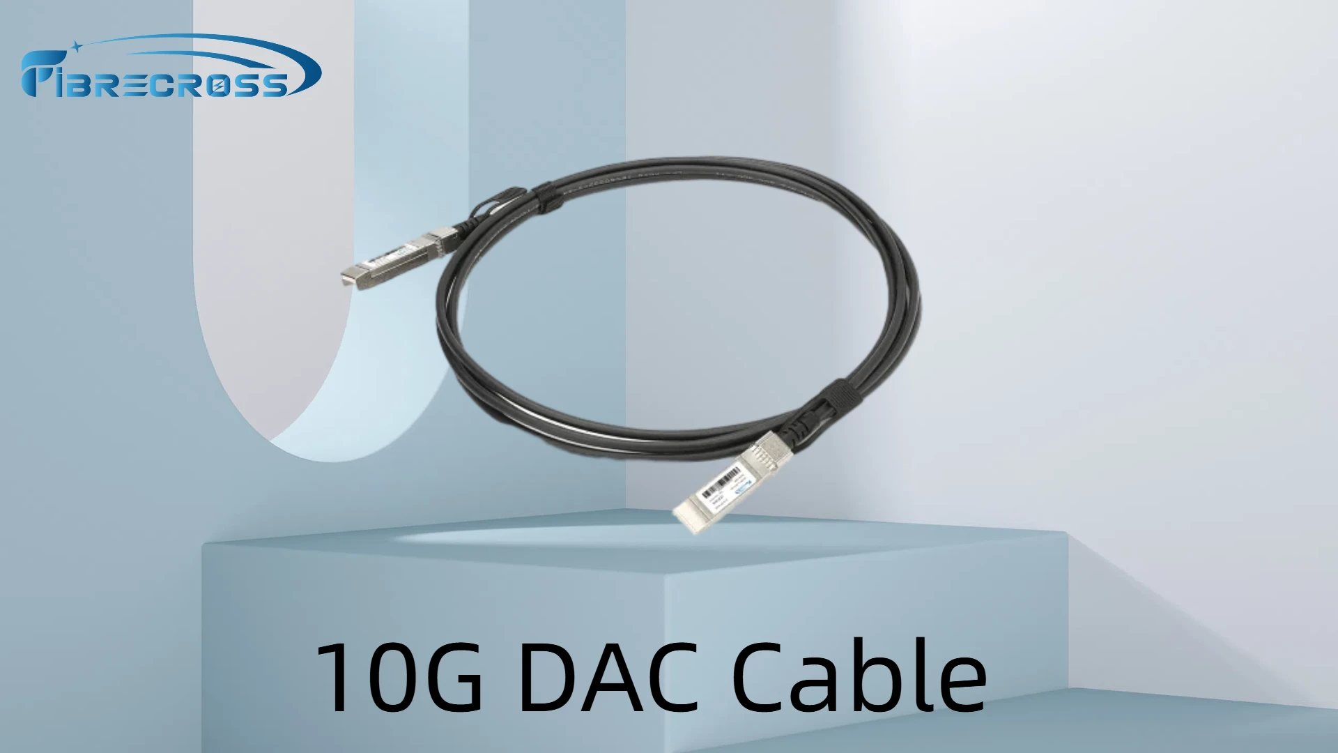
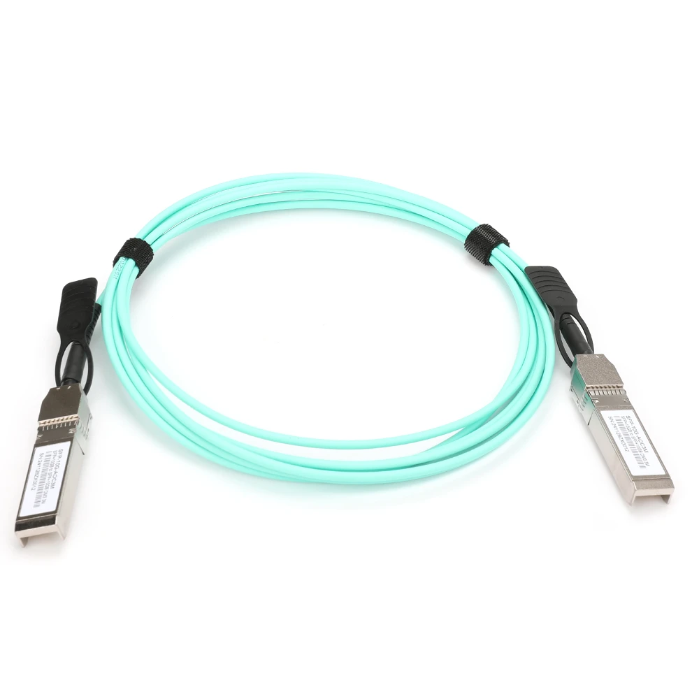
- “Direct Attach” refers to a fixed-length copper assembly in which the transceiver electronics (often QSFP, QSFP28, SFP+, etc.) are permanently integrated at each end of the cable. Unlike a separate transceiver module plugged into a switch and a separate copper patch cable, a DAC combines both into one unit.
- Because the transceivers are built into the cable ends, there’s no hot-swap of optics; if one end fails, the entire assembly must be replaced.
Twinax Copper Conductor
- Twinax Cable: A twinax (twin axial) cable has two conductors that carry a differential pair. Each conductor is insulated and twisted around a central axis, then shielded.
- Gauge (AWG): Typical DAC assemblies use 26–28 AWG copper. Thicker conductors (lower AWG number) reduce DC resistance but increase flexibility issues. The 26–28 AWG balance cost, flexibility, and loss characteristics for reaches up to around 5 meters.
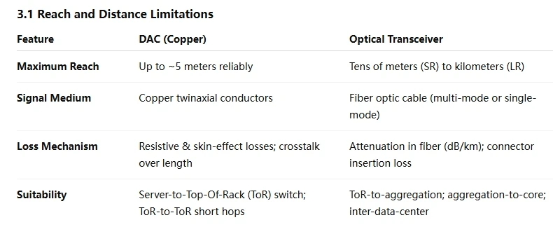
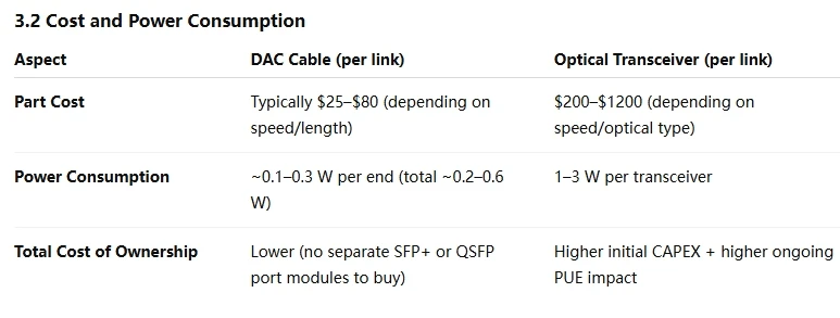
How DAC Cables Compare to Optical Transceivers
Primary Use Cases:
Server to Top-of-Rack (ToR) Switch
ToR to ToR or ToR to Aggregation (within same aisle)
Inside Storage Arrays or Compute Clusters
Limitations and Drawbacks
Maximum Reach
- Once distance exceeds ~5 meters at 25 Gbps-lane speeds (i.e., 100 Gbps QSFP28), copper becomes impractical due to bit-error-rate (BER) degradation. Running a 100 Gbps DAC at 5 m may already be at the edge of the vendor’s compliance spec (<10⁻¹² BER).
Flexibility
- Because each DAC is a fixed length, operators must maintain inventory of different lengths (0.5 m, 1 m, 2 m, 3 m, 5 m). If the data-hall layout changes, a new cable may be needed.
Lack of Field Upgradability
- If a DAC fails, one cannot replace just a broken fiber or re-terminate. The entire cable/transceiver assembly must be swapped out.
Weight and Rack-Cable Management
- In very dense racks with 48 QSFP28 DACs, the cumulative weight of copper can be substantial. Rack cable managers must account for copper’s lack of flexibility compared to thin LC duplex fibers.

Future Trends and Beyond
Ethernet Speeds Cranking Past 100 Gbps
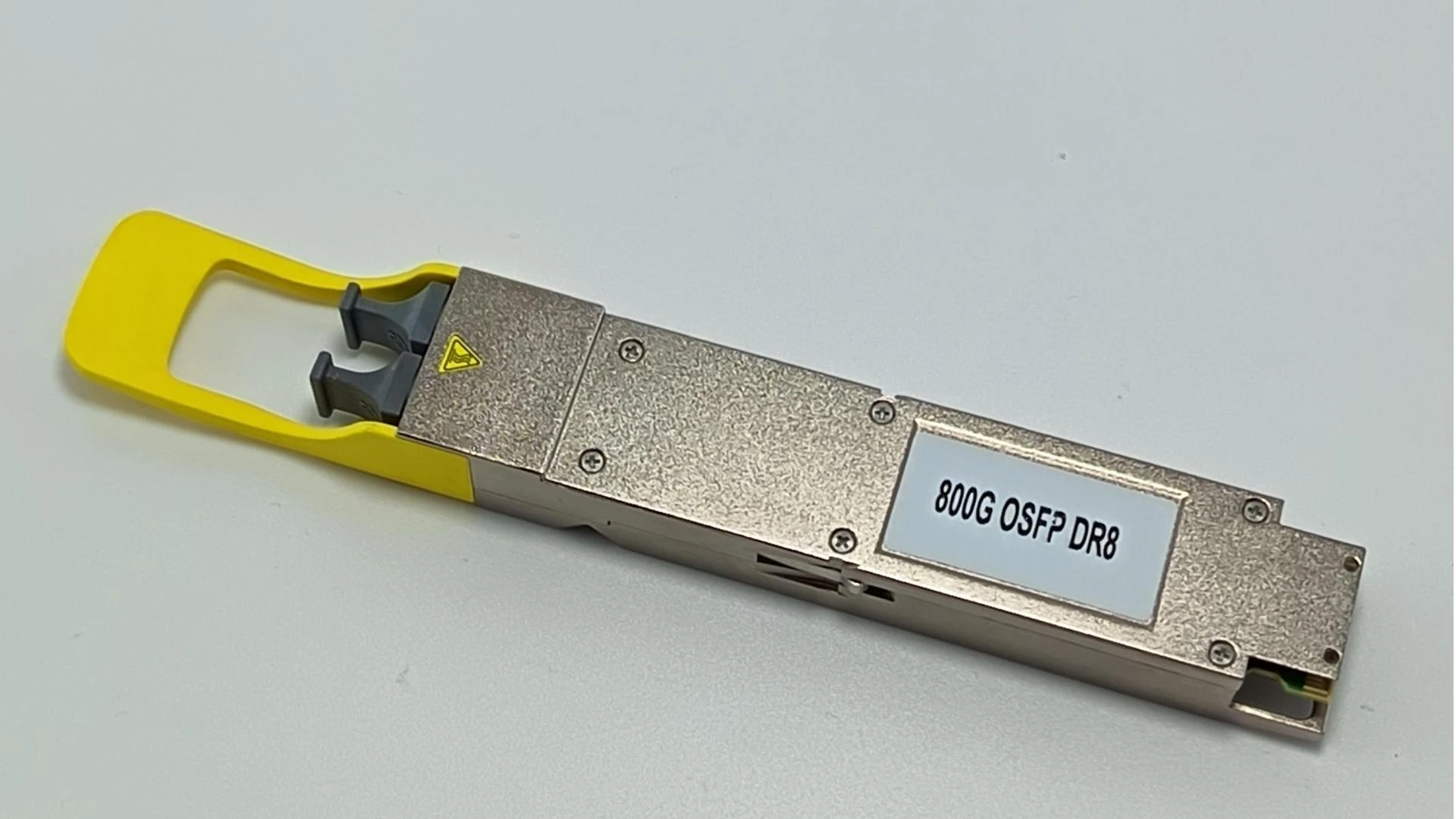
200 Gbps and 400 Gbps DACs: As 400 Gbps becomes common, QSFP56 (4 × 100 Gbps PAM4) and QSFP112 (2 × 200 Gbps PAM4) form-factors appear. Current 400 Gbps DACs are typically limited to 0.5 – 1 m due to the extreme losses at 100 GBd PAM4. Expect copper to remain viable up to 1 m in rack-side interconnects, but optical is inevitable for anything beyond that.
Next-Gen SerDes: Transceiver ASICs with improved equalization (CTLE, DFE) and better cable designs might extend copper reaches slightly, but they cannot eclipse the physical limits of copper’s conductivity and dielectric losses. By 800 Gbps and 1.6 Tbps per port (using 4 × 200 Gbps or 8 × 100 Gbps lanes of PAM4), copper distances will shrink to < 0.5 m, making optics the default for rack-to-rack connectivity.
Hybrid Approaches
Some data centers adopt hybrid ToR switches that have both QSFP28 ports (for DAC to local servers) and optical uplinks (e.g., QSFP28 LR4) for aggregation. As speeds increase, we’ll see more modular switch designs where line cards are swapped depending on whether short-reach DAC or long-reach optical is prioritized.
Emerging interconnects—like Silicon Photonics Direct Attach—combine optical engines directly onto the transceiver housing, dramatically reducing power consumption and potentially offering 1 m fiber runs that match copper latency. These will effectively merge the best of both worlds: short-reach optical that’s functionally identical to today’s passive DAC in terms of power and cost.
Conclusion
Direct Attach Copper (DAC) cables have cemented their place as a cost-effective, low-latency solution for very short-distance, high-speed links inside racks and between adjacent racks. Their simple twinax structure—shielded, fixed-length copper with integrated transceivers—keeps per-link costs and power budgets low, making them indispensable in hyperscale and enterprise environments where thousands of links exist.
However, as Ethernet speeds climb toward 400 Gbps and beyond, copper’s distance limitations become more pronounced. Breakout DACs continue to help maximize port utilization for multi-lane architectures, but ultimately, optical connectivity (either traditional pluggable optics or next-gen silicon photonics) will dominate rack-to-rack and data-center-to-data-center interconnects.


Sign in to leave a comment.