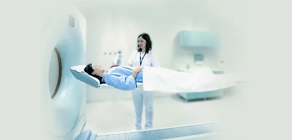
In some environments, temperature measurement does not fail because the process is too hot, too cold, or too complex. It fails because the sensor itself becomes part of the electrical problem. A probe that looks perfectly acceptable on a clean benchtop can become noisy, misleading, or unsafe the moment it enters an MRI suite, a high-voltage cabinet, a plasma chamber, or a microwave heating setup. MRI systems, for example, use a strong magnetic field that extends beyond the machine, and the FDA’s MRI safety evaluation framework specifically focuses on systems operating at 1.5 T/64 MHz and 3 T/128 MHz. In other words, these are not gentle environments for anything built around conductive measurement paths.
That is why the real comparison is not “new sensor versus old sensor.” It is “light-based sensing versus electrically vulnerable sensing.” In direct, in-field measurement jobs where electromagnetic interference is built into the application, fiber optics are not just a nice upgrade. They are often the only sensor architecture that can stay electrically passive, preserve signal integrity, and reach the spot that actually matters.
Key Takeaways
- In EMI-heavy environments, the lead wire can become part of the measurement problem.
- Fiber optic probes carry light, not electrical signal, so they stay immune to EMI, RF, microwave, and high-voltage interference.
- Fluorescence sensing is strong for true point hot-spot monitoring, while FBG sensing is stronger when multi-point or quasi-distributed data is needed.
- The right choice depends on field intensity, sensor placement, and whether the job needs one critical point or multiple sensing points.
What makes EMI-intensive applications so unforgiving?
An EMI-intensive application is any setup where the field around the process is strong enough to corrupt, heat, or destabilize a conventional electrical measurement path. That includes MRI-guided systems, power transformers, switchgear, RF ablation tools, semiconductor plasma tools, induction heating rigs, EMC test chambers, and microwave processing lines. In each of these settings, the environment is not just “busy.” It is actively interacting with metal leads, conductive loops, shielding, and grounding paths.
That detail matters because thermocouples and RTDs are not simply temperature tips. They are complete electrical systems. Their performance depends on metal conductors carrying a tiny signal back to electronics that must interpret it correctly. Once those conductors sit near strong RF, microwave, magnetic, or high-voltage sources, induced noise and unwanted current can blur the line between a real temperature change and a false electrical effect. Conventional sensors can also introduce heat conduction along the probe and may require more recalibration over time.
Why fiber optic sensors in EMI-intensive applications are different
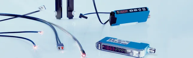
A fiber optic sensor measures by analyzing changes in light, not changes in electrical voltage or resistance. That single architectural shift changes everything. Glass fiber is non-conductive, electrically passive, chemically resistant, and largely invisible to the electromagnetic problems that distort conventional measurement. When the process demands direct sensing inside the field itself, that is the difference between a trustworthy reading and a misleading one.
A practical way to think about it is a simple reliability test.
- Electrical isolation
If the sensor must sit near high voltage, RF power, microwave energy, or a powerful magnetic field, the measurement path should not be conductive. - Signal integrity
If the measurement must stay clean while the process is energized, the signal should be immune to induced electrical noise. - True hot-spot access
If the most important temperature exists inside a winding, against a live joint, near a wafer, or inside an MRI-compatible device, the sensor must physically reach that point without becoming the hazard.
If a measurement problem fails even one of those tests, electrical sensing starts to look fragile. If it fails all three, fiber optics usually stop being optional.
| Environment | What usually goes wrong with electrical sensing | What fiber optics change | Best-fit sensing approach |
|---|---|---|---|
| MRI-guided systems | Conductive leads can distort readings or create safety concerns near strong magnetic and RF fields | Passive, non-conductive measurement path | Point sensing or multiplexed fiber array |
| Power transformers and switchgear | High voltage and electrical noise make direct sensing difficult | In-situ insulated hot-spot measurement | Robust point probe |
| RF and microwave heating | Field energy couples into metal leads | Clean measurement during active heating | Metal-free point probe |
| Semiconductor plasma tools | Noise, grounding complexity, and unstable feedback affect process control | Stable low-noise feedback at the measurement point | Fluorescence or other optical point sensing |
| EMC and validation labs | The sensor can disturb the test or be disturbed by it | Low-disturbance thermal verification | Fiber point probe or FBG array |
Which fiber-optic method fits the job best?
Two families matter most in real buying decisions. Fluorescence-based sensing is usually the better fit when the job is to monitor one critical hot spot with confidence. It works by sending an excitation pulse to a fluorescent material at the sensing tip and measuring how quickly that light decays back. Because the temperature information comes from the optical response at the tip, it is well suited to targeted measurement inside transformers, near energized medical tools, and in harsh process equipment.
Fiber Bragg Grating sensing works differently. A microscopic grating inside the fiber reflects a specific wavelength, and temperature shifts that reflected wavelength. That makes FBG especially useful when a team wants several sensing points along one fiber or needs a more multiplexed layout. It is powerful, but it also asks for clearer thinking about strain, packaging, and installation, because wavelength shifts can reflect more than one influence if the design is careless.
So the decision is not “Which technology is newer?” It is “Do you need one trusted point or many coordinated points?” That question saves time, budget, and rework.
The Correct Way Forward
A lot of teams make the same mistake at the start. They shop by temperature range first and field conditions second. That is backwards.
Do this: define the electromagnetic environment, the sensing location, and the access constraint first.
Not that: assume a traditional sensor will work because the nominal temperature is within range.
Do this: decide whether the process needs one true hot spot or several sensing points.
Not that: choose a multiplexed system just because it sounds more advanced.
Do this: ask whether the process can tolerate the sensor’s presence.
Not that: ignore probe material, routing, bend radius, or packaging until late in the project.
This is also where a short, relevant quote still holds up. Marie Curie wrote, “Nothing in life is to be feared, it is only to be understood.” In measurement work, that usually means understanding the environment before choosing the sensor.
A Practical Example from Daily Life
Picture a team validating a heating process inside an RF-driven setup. On paper, the thermocouple spec looks fine. In practice, the trace starts jittering as power ramps. The team slows the process, adds shielding, retries routing, and still cannot tell whether they are seeing real temperature behavior or electrical contamination. Once the sensing path shifts to optical, the argument changes. The sensor is no longer fighting the field. It is finally reporting the process. That is the point where troubleshooting becomes control.
Conclusion
When the sensing environment is electrically hostile, reliability starts with physics, not preference. A sensor that depends on metal conductors will always have more to defend against in MRI fields, RF energy, microwaves, induction zones, and high-voltage assets. A sensor that depends on light has a much cleaner starting point. That is why fiber optic sensors in EMI-intensive applications keep showing up wherever safety, control, and trust in the reading matter most.
For teams trying to match the right sensing method to a difficult application, BioTemp4Life can help evaluate the use case, support demonstrations and setup, and guide the choice between specialized temperature and dielectric measurement solutions.
FAQ
What makes a good fiber optic sensor for EMI-heavy work?
A good one stays electrically passive, reaches the true hot spot, and remains stable while the process is energized.
What are the best practices for sensor placement?
Place the probe where the thermal decision is made, not where access is easiest.
How do you choose between fluorescence and FBG sensing?
Choose fluorescence for one critical point. Choose FBG when several sensing points along one fiber matter more.
When should a team hire a specialist for a custom sensing setup?
When field conditions, installation limits, or compliance requirements make trial-and-error too risky or expensive.
Which services matter most during evaluation and setup?
Application review, probe selection, routing guidance, and support during validation matter most.
What are the top trends in harsh-environment fiber sensing?
More multi-parameter sensing, smarter data interpretation, and better integration into demanding industrial and medical systems.


Sign in to leave a comment.