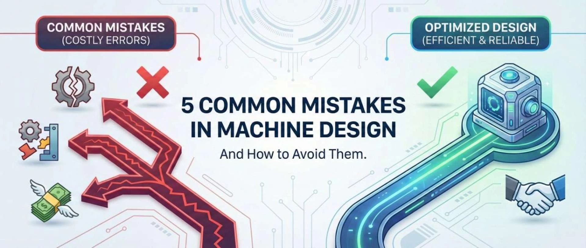
The High Stakes of the Drawing Board
In mechanical engineering, the design phase is where the battle for profitability is won or lost. It is well documented in the manufacturing industry that, while design accounts for only roughly 5% of a product's total cost, it determines 70% to 80% of the product’s final manufacturing cost.
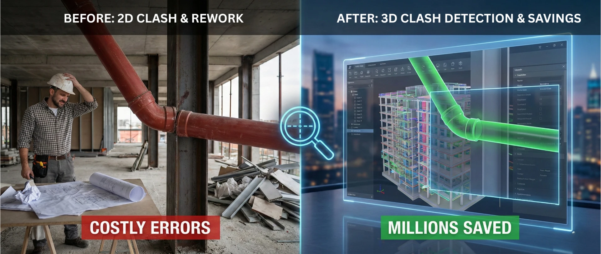
Once a machine moves from the CAD environment to the factory floor, the cost of rectifying an error skyrockets. A tolerance oversight that takes five minutes to fix in SolidWorks can cost thousands of dollars in scrapped tooling and delayed production schedules once steel has been cut.
For engineering leaders and product developers, the goal is not just to design a machine that works, but to design one that is reliable, manufacturable, and cost-effective. Yet, even seasoned engineers can fall into habitual traps that undermine these goals.
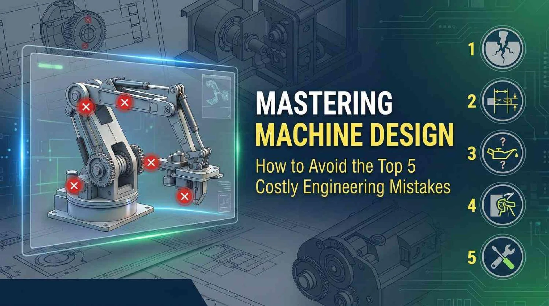
Let’s break down the five most common mistakes in machine design, and just as importantly, explore the strategies to avoid them as you move through each stage of the process.
1. Treating Design for Manufacturing (DFM) as an Afterthought
The most pervasive error in modern engineering is the "siloed" approach. This occurs when a design engineer focuses purely on functionality and geometry, finalising the 3D model before ever consulting the manufacturing team or a machinist.
The Mistake: Creating complex features that are unnecessarily difficult or impossible to machine. A classic example is designing square internal corners in a milled pocket. Since CNC milling tools are round and rotate, they cannot create a perfectly sharp internal corner without expensive specialised processes like Electrical Discharge Machining (EDM) or broaching.
The Consequence:
- Skyrocketing Costs: "Non-standard" features require custom tooling and longer cycle times.
- Production Delays: The design gets kicked back from the machine shop with a "no-bid" or a massive change order, triggering the dreaded engineering change loop.
The Solution: Concurrent Engineering. Adopt a Design for Manufacturing (DFM) mindset from day one.
- Consult Early: Bring your mechanical design services partner or manufacturing vendors into the concept phase. Ask them, "How would you hold this part?" and "What is the most expensive feature on this drawing?"
- Standardise: Design around standard tool sizes. If a 6mm end mill is standard, don't specify a corner radius of 2.9mm; set it to 3.1mm to allow the tool to turn without stopping, reducing chatter and wear.
2. The "Tight Tolerance" Trap
There is a natural tendency among engineers to associate "precision" with "quality." This leads to one of the most expensive habits in the industry: over-tolerancing.
The Mistake: Applying tight tolerances (e.g., ±0.005mm) to every dimension on a print, regardless of whether the feature interacts with another part.
The Consequence: Manufacturing costs grow exponentially as tolerances tighten. A hole with a standard tolerance might be drilled in seconds. A hole with a tight tolerance requires drilling, boring, and reaming, tripling the time required for operations and inspections. Furthermore, tight tolerances increase the scrap rate; if a part is 0.001mm out of spec, it must be discarded, even if that dimension has zero impact on the machine's function.
The Solution: Functional Tolerancing & GD&T
- Use GD&T: Geometric Dimensioning and Tolerancing (GD&T) provides more functional definitions (such as position, flatness, or parallelism) than just linear X/Y dimensioning. This often opens up the manufacturing window while ensuring the part still fits.
- Focus on Interfaces: Apply tight tolerances only to mating surfaces (bearings, dowel pins, sliding fits). For everything else, use a generous "block tolerance" (e.g., ±0.2mm) to speed up production.
3. Ignoring Material Selection Nuances
Selecting a material in a CAD menu is not true material selection. Machine design often fails when materials are chosen based on a single property, such as tensile strength, while critical environmental or processing factors are overlooked.
The Mistake: Overlooking secondary properties such as corrosion resistance, thermal expansion, or machinability. For instance, using generic carbon steel in a humid environment without accounting for plating, or selecting a super-alloy that is incredibly strong but destroys cutting tools, driving up machining costs by 500%.
The Consequence:
- Premature Failure: Galvanic corrosion can occur when two dissimilar metals (such as stainless steel and aluminium) are placed in contact with an electrolyte, leading to rapid seizure or degradation of the assembly.
- Thermal Locking: If a machine operates at high temperatures, a steel shaft inside an aluminium housing may seize because aluminium expands roughly twice as much as steel.
The Solution: The "Life-Cycle" Material Audit
- Environmental Check: Analyse the operating environment (temperature, humidity, chemical exposure) before freezing the design.
- Process Compatibility: Ensure the material is compatible with the manufacturing method. Don't specify a difficult-to-weld alloy for a welded frame.
- Reference Databases: Utilise standard material property databases (like MatWeb) to verify fatigue limits and thermal coefficients, ensuring the material can survive the machine's expected lifecycle.
4. Skipping Analysis and Simulation (The "Build and Break" Method)
In the past, engineers relied on "over-engineering," making parts twice as thick as necessary to ensure safety. In 2026, this is a waste of material and energy. Conversely, relying solely on intuition without validation leads to catastrophic failures under load.
The Mistake: Underestimating dynamic loads and fatigue. A static load calculation might show a safety factor of 2.0, but it fails to account for vibration, thermal cycling, or shock loads that occur during real-world operation.
The Consequence: Field failures are the most expensive type of error. They result in warranty claims, reputation damage, and potential safety lawsuits. A shaft that snaps after 10,000 cycles because of ignored stress concentrations is a preventable disaster.
The Solution: Use Virtual Prototyping by following a set process. Begin by integrating Finite Element Analysis (FEA) and Motion Analysis early in the design stage, not just at the end. Identify areas of concentrated stress, such as sharp corners, and adjust geometry as needed, adding radii to enhance fatigue life. Simulate all real-world loading conditions, including vibration, startup torques, emergency stops, and thermal effects, to ensure robust design.
- Identify Stress Risers: FEA will instantly highlight "hot spots" where sharp corners or abrupt geometry changes are concentrating stress. Adding a simple fillet radius in these areas can often double the part's fatigue life.
- Simulate Reality: Don't just testy for gravity; testy for startup torques, emergency stops, and thermal expansion.
5. Forgetting the Human Element: Assembly and Maintenance
A machine is not finished when it is assembled in the CAD software; it is finished when it is running on the client's floor and can be serviced by a technician.
The Mistake: Designing "impossible assemblies." This happens when a bolt head is placed where no wrench can reach it, or a critical wear part (like a filter or belt) requires disassembling the entire machine to replace it.
The Consequence:
- Assembly Nightmare: If a technician needs "tiny fingers" or special custom tools to assemble the product, labour costs will balloon.
- Client Frustration: If a $50 maintenance task takes 4 hours of downtime because of poor accessibility, the customer will likely look elsewhere for their next machine.
The Solution: Design for Assembly (DFA) & Serviceability
- The "Tool Check": Visually inspect your 3D model to ensure there is clearance for standard wrenches and screwdrivers around every fastener.
- Modular Design: Design sub-assemblies that can be built offline and dropped into the main frame. This creates parallel workflow streams on the assembly floor, drastically reducing build time.
- Wear Part Access: Place fuses, filters, and lubrication points on the outside of the machine or behind quick-release panels.
Engineering for the Real World
Avoiding these five mistakes requires a shift in perspective. It demands that engineers look beyond the screen and consider the entire lifecycle of the machine, from the machinist cutting the steel to the technician replacing a belt five years later.
By integrating DFM, respecting material science, and validating designs with simulation, you don't just avoid errors; you build a reputation for excellence.
Is your next project ready for production? Partner with Tesla Mechanical Designs to ensure your machinery is optimised for cost, performance, and manufacturability.


Sign in to leave a comment.