
A pneumatic cylinder converts compressed air pressure into a linear pushing or pulling force, calculated as F = P × A, where P is air pressure and A is the piston's circular area (π × r²). A standard 50 mm bore cylinder running at 6 bar (600,000 Pa) produces a theoretical push force of 1,178 Newtons, roughly enough to lift a 120 kg load. That single formula drives everything from robotic arms on car assembly lines to the filling heads on your bottled-water production line.
If you work in manufacturing, automation, or industrial engineering — or you're simply curious about what makes factory machines move — this guide breaks down exactly how these devices work, the math behind them, and where they're used every day.
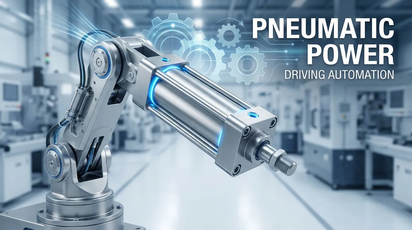
What Is a Pneumatic Cylinder?
A pneumatic cylinder (also called an air cylinder or pneumatic actuator) is a mechanical device that uses pressurized air to generate controlled, linear motion. Feed it compressed air; it pushes or pulls with a measurable force. Release the air; it retracts.
The concept is the same as pushing a syringe plunger with your thumb — the air you compress behind the plunger creates a force proportional to the pressure and the plunger's area. Scale that up to industrial pressures (4–10 bar is typical), add precision machining, and you have one of the most reliable motion-control tools in modern manufacturing.
Pneumatic cylinders sit at the intersection of physics and practical engineering. They're a natural topic for anyone exploring technology and automation (https://writeupcafe.com/topic/technology) — a field that's reshaping how goods are made worldwide.
Core Components of a Pneumatic Cylinder
Understanding how a pneumatic cylinder works starts with its five key parts:
Cylinder barrel (bore): The main hollow tube where the piston travels. Its internal diameter — the bore — is the most important dimension for force calculations. Barrels are typically machined from aluminum alloy or stainless steel for smoothness and air-tightness.
Piston: The disc-shaped component inside the barrel that separates the two air chambers. Compressed air pushes against one face of the piston, generating force. Piston seals prevent air from leaking between chambers.
Piston rod: The rod extends through the front cap and connects to the load you want to move. It transmits the piston's force to the outside world. Rod diameter matters on the return stroke — it reduces the effective piston area.
End caps: Two end caps (front and rear) seal the barrel. Each has one or more ports through which air enters and exits.
Ports and seals: Air inlet/outlet ports connect to your compressed-air supply via solenoid valves. Internal seals keep everything airtight and reduce friction losses.
Types of Pneumatic Cylinders
Not all pneumatic cylinders work the same way. Three types dominate manufacturing:
Single-Acting Cylinders
In a single-acting cylinder, compressed air enters through one port and pushes the piston in only one direction — typically outward (extension). A return spring pushes the piston back when air pressure is released.
Best for: Clamping, stamping, and applications where only one direction requires powered force. Simpler, cheaper, and uses less air — but the spring limits the maximum stroke length and reduces effective force.
Double-Acting Cylinders
A double-acting cylinder has two ports — one on each side of the piston. Compressed air drives the piston in both directions, giving you powered extension and powered retraction. This is the most common type in manufacturing.
Best for: Repetitive motion, conveyor indexing, robotic pick-and-place, and any task requiring precise control in both directions. More versatile and faster than single-acting designs.
Rodless Cylinders
In a rodless cylinder, the piston is coupled to an external carriage via a magnetic or mechanical slot — no rod protrudes from the barrel. This makes them ideal for long stroke applications where a conventional rod would buckle or require too much space.
Best for: Long-travel linear transport (3–6 m strokes), CNC axis drives, and clean-room environments where a protruding rod is impractical.
For a deeper look at how these mechanical systems connect to broader science and technology (https://writeupcafe.com/topic/science-technology) applications, WriteUpCafe has an active community of engineering and STEM writers worth exploring.
How to Calculate Pneumatic Cylinder Force — With Real Numbers
This is where most online guides let engineers down. Let's fix that with full worked examples in both metric and imperial units.
The Force Formula
Theoretical Force = Pressure × Piston Area
F = P × (π × r²)
Where:
- F = force (Newtons or pounds-force)
- P = air pressure (Pascals or PSI)
- r = piston radius = bore diameter ÷ 2 (meters or inches)
- π ≈ 3.14159
Real-world effective force is typically 85–90% of theoretical due to friction from seals and internal components. Always apply this efficiency factor for practical sizing.
Worked Example 1 : Metric System (mm, bar, Newtons)
Scenario: You need to select a pneumatic cylinder to clamp a workpiece during CNC machining. Your compressed air supply is 6 bar. You're considering a 50 mm bore cylinder.
Step 1 — Convert pressure to Pascals:
6 bar = 600,000 Pa
Step 2 — Calculate piston radius:
Bore = 50 mm → r = 25 mm = 0.025 m
Step 3 — Calculate piston area:
A = π × r² = 3.14159 × (0.025)² = 3.14159 × 0.000625 = 0.001963 m²
Step 4 — Calculate theoretical force:
F = 600,000 × 0.001963 = 1,178 N
Step 5 — Apply efficiency factor (85%):
Effective force = 1,178 × 0.85 = 1,001 N (≈ 102 kg load capacity)
Conclusion: A 50 mm bore cylinder at 6 bar can reliably clamp a 100 kg workpiece with a small safety margin.
Worked Example 2: Imperial System (inches, PSI, lbf)
Scenario: An automotive assembly plant needs a cylinder to lift a 200 lb fixture. The air supply is 80 PSI. What bore diameter is needed?
Step 1 — Determine required force (add 25% safety factor):
Required force = 200 × 1.25 = 250 lbf
Step 2 — Rearrange formula to find area:
A = F ÷ P = 250 ÷ 80 = 3.125 in²
Step 3 — Find required radius:
A = π × r² → r² = 3.125 ÷ π = 0.9947 → r = 0.997 inches
Step 4 — Calculate bore diameter:
D = 2 × r = 1.99 inches → round up to 2-inch bore
Step 5 — Verify with 2-inch bore:
A = π × 1² = 3.1416 in²
Theoretical force = 80 × 3.1416 = 251.3 lbf
Effective force = 251.3 × 0.85 = 213.6 lbf
Note: Since effective force (213.6 lbf) is below the 250 lbf target, step up to a 2.5-inch bore or increase line pressure to 100 PSI.
This is precisely the kind of calculation that gets skipped in the field — and leads to cylinder failures. For quick verification of these numbers, engineers often use an online tool; check it out here for cylinder geometry and volume reference.
Return Stroke Force (Double-Acting Cylinders)
On the return stroke, the piston rod occupies space inside the bore — reducing effective area and therefore force. The formula adjusts to:
F_return = P × π/4 × (D² − d²)
Where D = bore diameter and d = rod diameter.
Example: 50 mm bore, 20 mm rod, 6 bar:
- A_return = π/4 × (50² − 20²) = π/4 × (2500 − 400) = π/4 × 2100 = 1,649 mm²
- F_return = 600,000 Pa × 0.001649 m² = 989 N (vs. 1,178 N on extension)
Always account for this asymmetry when the return stroke must do work.
---
How to Choose the Right Bore Size
Selecting the wrong bore size is one of the most expensive mistakes in pneumatic system design. Here's a practical decision framework:
1. Define your load force. Weigh or calculate the load in Newtons or lbf. Add a safety factor of 25–50% for dynamic applications (conveyor indexing, rapid cycling) or 15–25% for static clamping.
2. Know your supply pressure. Most factories run 6–8 bar (87–116 PSI). Work with what you have — don't assume you can always increase pressure.
3. Calculate minimum bore. Use D = 2 × √(F / (P × π)) rearranged from the force formula.
4. Select the next standard size up. Standard bore sizes follow ISO 15552 increments: 12, 16, 20, 25, 32, 40, 50, 63, 80, 100, 125, 160, 200, 250 mm.
5. Check stroke and buckling. For long strokes (> 300 mm at small bore sizes), verify the rod won't buckle under compressive load using Euler's buckling formula.
This decision process is a great fit for business and engineering education (https://writeupcafe.com/topic/education) discussions, where practical frameworks like this outperform pure theory.
Real-World Manufacturing Applications
Pneumatic cylinders show up in virtually every production environment. Here's where you'll find them and what they're doing:
Assembly lines: Extending and retracting to position components, press-fit parts together, or advance index tables one station at a time. A typical automotive body shop has hundreds of cylinders operating in synchronized sequences with cycle times under 1 second.
Packaging machinery: Sealing heads, labeling arms, box-folding mechanisms, and carton ejectors all rely on pneumatic actuation. The clean, oil-free exhaust makes them ideal for food and pharmaceutical packaging where contamination is a zero-tolerance issue.
Clamping and fixturing: CNC machining centers use pneumatic clamp cylinders to hold workpieces rigidly during cutting. The hold force is calculated precisely — too little and the part moves; too much and you risk distorting thin-walled components.
Valve actuation: In piping systems across chemical plants, water treatment facilities, and refineries, pneumatic cylinders open and close large gate or butterfly valves. They're preferred here because compressed air is inherently non-sparking — safe in explosive atmospheres where electric actuators are prohibited.
Robotics: Collaborative robots (cobots) and industrial robot end-effectors use compact pneumatic grippers, essentially miniaturized double-acting cylinders — to grasp, hold, and release parts at high speed.
The breadth of these business applications (https://writeupcafe.com/topic/business) across industries explains why the global pneumatic cylinder market continues to expand alongside industrial automation investment.
Common Mistakes Engineers Make
Even experienced technicians fall into these traps:
Using diameter instead of radius in the area formula. The formula uses r (radius = D/2). Using the full diameter instead of radius will quadruple your calculated force — a dangerous overestimate. Always halve the bore diameter before squaring.
Ignoring the efficiency factor. Theoretical force assumes zero friction. Real cylinders lose 10–15% to seal drag, especially at low pressures or with worn seals. Never size a cylinder to theoretical force alone.
Forgetting the return stroke asymmetry. If your double-acting cylinder must do work in both directions, check the return stroke force separately. It's always lower than the extension force.
Mixing units. If pressure is in bar and bore is in mm, convert consistently before calculating. 1 bar = 100,000 Pa; mm must convert to meters for SI calculations. A mixed-unit calculation is a guaranteed path to wrong answers.
Ignoring acceleration forces. For fast-cycling applications, the force needed to accelerate the load (F = ma) adds to the static load requirement. At short cycle times, this can represent 20–30% of total force demand.
FAQs
Q: What is the basic formula to calculate pneumatic cylinder force?
A: The formula is F = P × A, where F is force (in Newtons or lbf), P is air pressure (in Pascals or PSI), and A is the piston area (π × r²). For a 50 mm bore cylinder at 6 bar: A = π × 0.025² = 0.001963 m², and F = 600,000 × 0.001963 = 1,178 N. Always multiply by an efficiency factor of 0.85–0.90 for real-world sizing.
Q: What's the difference between single-acting and double-acting pneumatic cylinders?
A: A single-acting cylinder uses air pressure to move the piston in one direction only; a spring returns it when air is released. A double-acting cylinder uses air pressure for both extension and retraction, giving you powered control in both directions. Double-acting cylinders are far more common in manufacturing because they're faster, more controllable, and work for longer strokes where a return spring would be impractical.
Q: What air pressure do most industrial pneumatic cylinders use?
A: Most factory systems run at 6–8 bar (87–116 PSI), with 6 bar being the most common standard. Some precision applications run as low as 2–3 bar, and heavy-duty systems can operate up to 10 bar. Increasing pressure increases force linearly — but also increases air consumption and wear on seals.
Q: How does bore diameter affect the force output?
A: Force scales with the square of the radius, meaning bore diameter has a dramatic effect. Doubling the bore diameter quadruples the piston area and therefore quadruples the theoretical force at the same pressure. This is why selecting bore size is the primary design decision in pneumatic system engineering. The Khan Academy geometry section (https://www.khanacademy.org/math/geometry) on circles and areas is a useful refresher on why the r² relationship matters so much here.
Q: Why is the return stroke force lower on a double-acting cylinder?
A: The piston rod occupies part of the bore cross-section on the back face of the piston. This reduces the effective area that air pressure pushes against during retraction. Use the formula F_return = P × π/4 × (D² − d²), where D is bore diameter and d is rod diameter. For a 50 mm bore with a 20 mm rod at 6 bar, return force is approximately 989 N versus 1,178 N on extension — a 16% reduction.
Q: Can I use the cylinder volume formula to size a pneumatic cylinder?
A: Cylinder bore volume (V = π × r² × h, where h is stroke length) tells you how much compressed air the cylinder consumes per stroke — critical for sizing your compressor and calculating operating costs. Engineers check it out here (https://www.cylindervolume-calculator.com/) to cross-check displacement volumes alongside force calculations. For force sizing alone, the F = P × A formula is what matters.
Q: What materials are pneumatic cylinder barrels made from?
A: The barrel (bore tube) is typically precision-machined aluminum alloy for standard applications — lightweight and corrosion-resistant. Stainless steel is used in food processing, pharmaceutical, and marine environments. Hard-anodized aluminum provides a middle ground — standard weight with improved wear resistance. The interior surface is honed to a mirror finish to minimize seal friction and ensure air-tightness.
Q: How do I prevent pneumatic cylinder failures in manufacturing?
A: The most common causes of cylinder failure are contaminated air (moisture and particulates degrade seals), excessive side loading (misalignment creates uneven seal wear), operating at the extreme ends of the pressure range, and inadequate lubrication. Fit inline air dryers and filters, ensure the cylinder is aligned coaxially with the load, and follow the manufacturer's lubrication intervals. Most modern cylinders use self-lubricating polymer seals that reduce — but don't eliminate — maintenance requirements.


Sign in to leave a comment.